Rectangular field diaphragm installation and alignment device and method of coaxial optical system

A technology of optical system and field diaphragm, which is applied in the field of aerospace optics, can solve the problems affecting the imaging of the target by the optical system, and achieve the effect of improving imaging quality, simple installation and alignment device, and easy mass assembly and adjustment

Active Publication Date: 2021-02-12
CHANGCHUN INST OF OPTICS FINE MECHANICS & PHYSICS CHINESE ACAD OF SCI
View PDF4 Cites 2 Cited by
  • Summary
  • Abstract
  • Description
  • Claims
  • Application Information

AI Technical Summary

Problems solved by technology

The field diaphragm is located on the primary image plane of the primary and secondary mirrors of the coaxial system, and there is a corresponding conjugate relationship between the primary image plane and the detector image plane. If the alignment problem between the field diaphragm and the detector is not solved, on the one hand The introduction of stray light outside the field of view into the imaging field of the detector, on the other hand, will cause the edge edge of the field diaphragm to be imaged on the detector, thereby producing an image of the field diaphragm and affecting the imaging of the target by the optical system

Method used


Image

  • Rectangular field diaphragm installation and alignment device and method of coaxial optical system
  • Rectangular field diaphragm installation and alignment device and method of coaxial optical system
  • Rectangular field diaphragm installation and alignment device and method of coaxial optical system

Examples


Embodiment 1

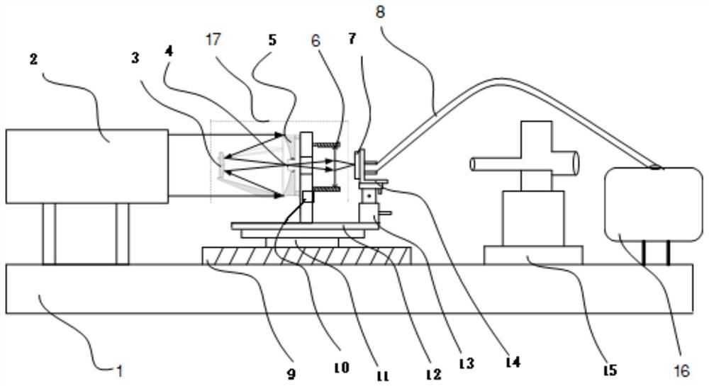
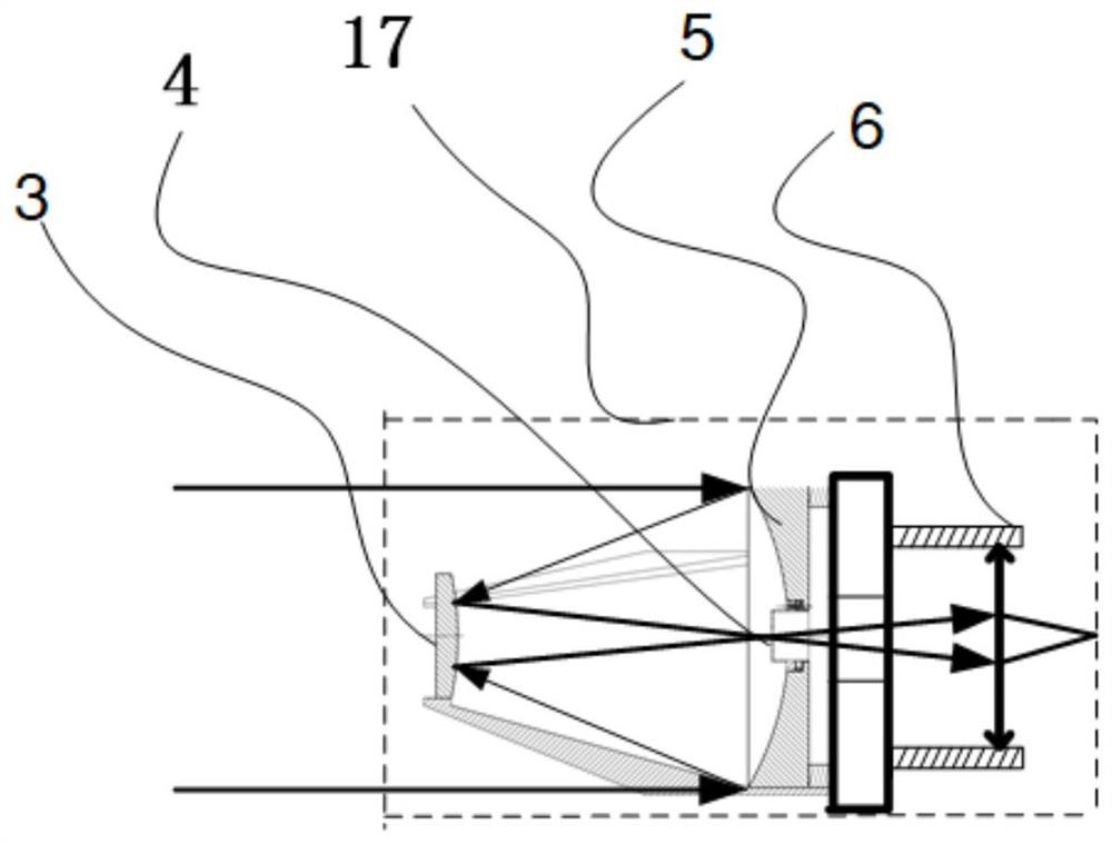
[0041] like Figure 1-Figure 3As shown, the collimator 2, the azimuth turntable 9, theodolite 15 and the image acquisition system 16 are sequentially arranged on the platform 1; the installation surface of the azimuth turntable 9 is parallel to the platform 1, and an azimuth and pitch adjustment platform 11 is arranged on the installation surface , the azimuth turntable 9 can rotate on its own axis, the azimuth and pitch adjustment table 11 can move on the two-dimensional plane where the installation surface is located, and can also adjust the angle with the two-dimensional plane where the installation surface is located; the optical system reference tooling 12 It is an inverted T-shaped or L-shaped structure, and its installation surface is fixed on the azimuth and pitch adjustment table 11; the optical system 17 passes through the surface perpendicular to the installation surface of the optical system reference tool 12 and is fixed; the five-dimensional detector adjustment fr...

Embodiment 2

[0044] Figure 4 The flowchart of the method for installing and aligning the rectangular field diaphragm of the coaxial optical system according to the second embodiment of the present invention is shown.

[0045] like Figure 4 As shown, the method for installing and aligning a rectangular field diaphragm of a coaxial optical system according to Embodiment 2 of the present invention includes the following steps:

[0046] S1. Adjust to make the collimator, optical system, and theodolite coaxial.

[0047] S2. Using the installation reference of the optical system drawn out by the cube prism to realize the coaxiality of the optical system and the collimator.

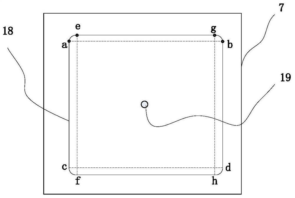
[0048] S3. Adjust the large target surface detector so that the optical system and the large target surface detector are aligned and aligned in the direction of rotation around the optical axis.

[0049] S4. Adjust the position of the field of view diaphragm according to the difference in pixel coordinates until the abs...


PUM


Abstract

The invention relates to the technical field of aerospace optics, and provides a rectangular field diaphragm installation and alignment device and alignment method of a coaxial optical system. The device comprises a platform, a collimator fixed on the platform, a theodolite, an image acquisition system, a detector supporting tool fixed on a five-dimensional detector adjusting frame, a large-target-surface detector mounted on the detector supporting tool, and an optical system mounting reference tool for fixing the five-dimensional detector adjusting frame, and an optical system and a cubic prism which are fixed on the optical system mounting reference tool. The invention provides a rectangular field diaphragm installation and alignment device and method of the coaxial optical system, wherein the device and method can realize accurate alignment of a rectangular detector and a rectangular field diaphragm at a primary image surface of primary and secondary mirrors of the coaxial optical system.

Description

technical field [0001] The invention relates to the technical field of aerospace optics, in particular to a device and method for installing and aligning a rectangular field of view diaphragm of a coaxial optical system. Background technique [0002] With the gradual development of aerospace optical system loads in the direction of light weight, high rigidity and high stability, coaxial optical systems are widely used in aerospace optical loads, whether it is a coaxial all-reflective optical system or a coaxial catadioptric optical system. Both include two-mirror optical systems (that is, include primary mirrors and secondary mirrors). In order to suppress stray light outside the field of view of the optical system, a field diaphragm is usually set at the primary image plane of the two-mirror system. The function of the field diaphragm can be The stray light outside the field of view is suppressed from entering into the imaging field of view, thereby improving the signal-to-...

Claims


Application Information

Patent Timeline
Patent Type & Authority Applications(China)
IPC IPC(8): G02B27/30G02B27/32
CPCG02B27/30G02B27/32
Inventor 谭双龙张新吴洪波胡铭钰王灵杰赵尚男刘洋
Owner CHANGCHUN INST OF OPTICS FINE MECHANICS & PHYSICS CHINESE ACAD OF SCI
Why Eureka
Try Eureka