Surface-mounted-built-in bearingless permanent magnet synchronous motor based on combined magnetic poles

A technology of permanent magnet synchronous motor and combined magnetic poles, which is applied in the field of surface-mounted-built-in bearingless permanent magnet synchronous motors based on combined magnetic poles, and the field of combined magnetic pole rotor structure, which can solve the problems of harmonic irreversible demagnetization and motor performance degradation, etc. , to achieve the effects of reducing stator iron loss, reducing distortion rate, and easy processing

Pending Publication Date: 2021-02-12
HANGZHOU ZHOUJU ELECTRONICS TECHNOLOGICAL
View PDF2 Cites 8 Cited by
  • Summary
  • Abstract
  • Description
  • Claims
  • Application Information

AI Technical Summary

Problems solved by technology

[0005] The purpose of the present invention is to solve the problem of harmonics and local irreversible demagnetization in the air-gap magnetic field of the bearingless rare earth permanent magnet synchronous motor driven by sine waves, especially in Under high t

Method used


Image

  • Surface-mounted-built-in bearingless permanent magnet synchronous motor based on combined magnetic poles
  • Surface-mounted-built-in bearingless permanent magnet synchronous motor based on combined magnetic poles
  • Surface-mounted-built-in bearingless permanent magnet synchronous motor based on combined magnetic poles

Examples


Embodiment 1

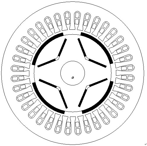
[0024] Embodiment 1: as figure 2 , Figure 5 with Image 6 As shown, a surface-mounted-built-in bearingless permanent magnet synchronous motor based on combined magnetic poles includes a rotor and a stator. The rotor is arranged inside the stator, and a radial air gap is left between the rotor and the stator. The stator includes a stator core 1 And the stator winding, the stator winding is arranged in the inner stator slot of the stator core, the stator winding includes the torque winding 2 and the suspension force winding 3, the rotor includes a plurality of rotor poles and the rotor core 4, and the outer surface of the rotor core 4 is evenly surface-mounted A plurality of rotor poles 5 are provided, and a layer of V-shaped permanent magnet installation grooves is evenly distributed along the circumferential direction inside the rotor core. The V-shaped permanent magnet installation grooves extend along the axial direction, and the V-shaped opening faces the stator. Each V-...

Embodiment 2

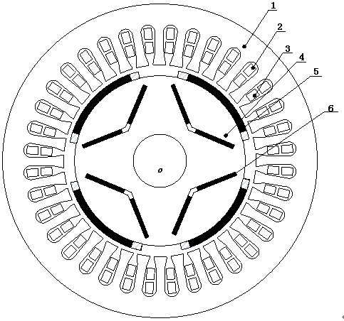
[0033] Embodiment 2: as image 3 , Figure 5 with Image 6 As shown, a surface-mounted-built-in bearingless permanent magnet synchronous motor based on combined magnetic poles includes a rotor and a stator. The rotor is arranged inside the stator, and a radial air gap is left between the rotor and the stator. The stator includes a stator core 1 And the stator winding, the stator winding is arranged in the inner stator slot of the stator core, the stator winding includes the torque winding 2 and the suspension force winding 3, the rotor includes a plurality of rotor poles and the rotor core 4, and the outer surface of the rotor core 4 is evenly surface-mounted A single magnetic pole 5 is set, and a layer of V-shaped permanent magnet installation grooves is evenly distributed along the circumferential direction inside the rotor core. The V-shaped permanent magnet installation grooves extend along the axial direction, and the V-shaped opening faces the stator. Combining magneti...

Embodiment 3

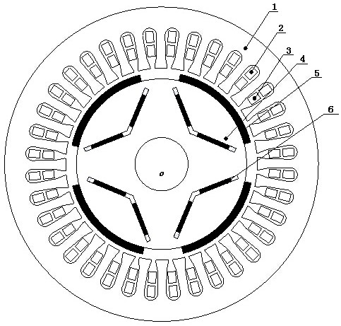
[0042] Embodiment 3: as Figure 4 , Figure 5 with Image 6 As shown, a surface-mounted-built-in bearingless permanent magnet synchronous motor based on combined magnetic poles includes a rotor and a stator. The rotor is arranged inside the stator, and a radial air gap is left between the rotor and the stator. The stator includes a stator core 1 And the stator winding, the stator winding is arranged in the inner stator slot of the stator core, the stator winding includes the torque winding 2 and the suspension force winding 3, the rotor includes a plurality of rotor poles and the rotor core 4, and the outer surface of the rotor core 4 is evenly surface-mounted The combined magnetic pole 5 is set, and a layer of V-shaped permanent magnet installation grooves is evenly distributed along the circumferential direction inside the rotor core. The V-shaped permanent magnet installation grooves extend along the axial direction, and the V-shaped opening faces the stator. Each V-shaped...


PUM


Abstract

The invention discloses a surface-mounted built-in bearingless permanent magnet synchronous motor based on combined magnetic poles. The motor comprises a rotor and a stator; the rotor is arranged in the stator; an air gap is reserved between the rotor and the stator; the stator comprises an iron core and a stator winding; the stator winding is arranged in an internal stator slot of the stator core; the stator winding comprises a torque winding and a suspension force winding; the rotor comprises a rotor structure body, built-in permanent magnets and surface-mounted permanent magnets, wherein the built-in permanent magnets and the surface-mounted permanent magnets can be both of combined magnetic pole structures. The permanent magnet synchronous motor is simple in structure; the permanent magnets of the motor are easy to machine; the air gap flux density waveform distortion rate of the motor is reduced; and the air gap flux density waveform of the combined magnetic pole type surface-mounted built-in bearingless permanent magnet synchronous motor is more sinusoidal than that of a traditional surface-mounted built-in bearingless rare earth permanent magnet synchronous motor, and therefore, the stator iron loss, the torque ripple and the suspension force ripple are reduced; and due to the strong demagnetization resistance of a ferrite material, the demagnetization risk during the operation of the motor is reduced, and the reliability of the motor is improved.

Description

technical field [0001] The invention relates to a combined magnetic pole type rotor structure, which belongs to the field of bearingless permanent magnet synchronous motors; in particular, it relates to a surface mount-built-in bearingless permanent magnet synchronous motor based on combined magnetic poles. Background technique [0002] The bearingless permanent magnet synchronous motor uses two sets of windings with different pole pairs (torque winding and suspension winding) in the stator slot to work together to generate a magnetic field. The magnitude and direction of the suspension force can be controlled by controlling the magnitude and direction of the superimposed synthetic magnetic field. The magnetic bearing has the advantages of no mechanical friction between the stator and the rotor, no lubrication, low operating noise, long service life, etc., and at the same time inherits the excellent characteristics of the permanent magnet synchronous motor. It has a simple ...

Claims


Application Information

Patent Timeline
IPC IPC(8): H02K1/02H02K1/27H02K1/16
CPCH02K1/02H02K1/16H02K1/274H02K1/276H02K2213/03
Inventor 郝正杰杨阳徐世文
Owner HANGZHOU ZHOUJU ELECTRONICS TECHNOLOGICAL
Why Eureka
Try Eureka