
Combined synchronous generator base and machining method thereof

A synchronous generator and combined technology, which is applied in the manufacture of motor generators, electrical components, electromechanical devices, etc., can solve the problems of difficulty in guaranteeing machining accuracy, difficulty in machine base machining, and long machining cycle, and achieve short machining cycle and improved R&D capabilities and the effect of fewer processes

Active Publication Date: 2021-02-12
ZHENJIANG ZHONGCHUAN XIANDAI GENERATING EQUIP CO LTD
View PDF9 Cites 2 Cited by
  • Summary
  • Abstract
  • Description
  • Claims
  • Application Information

AI Technical Summary

Problems solved by technology

At present, the machine base is usually of integral structure, but as the power of the generator increases, the size of the machine base increases accordingly, and the size of some machine bases has exceeded the stroke of machining equipment such as boring machines and vertical lathes, resulting in difficulties in machining the machine base. It can’t even be processed. Even if it can be processed by turning the machine base over, the machining accuracy is often difficult to guarantee, and the processing cycle is long. Large machine bases need to purchase large equipment to complete the normal processing, which will greatly increase the cost.

Method used


Image

  • Combined synchronous generator base and machining method thereof
  • Combined synchronous generator base and machining method thereof
  • Combined synchronous generator base and machining method thereof

Examples


Embodiment Construction

[0044] The present invention will be further described below in conjunction with drawings and embodiments.

[0045] In this embodiment, the driving end of the generator seat is the front, and the non-driving end is the rear.

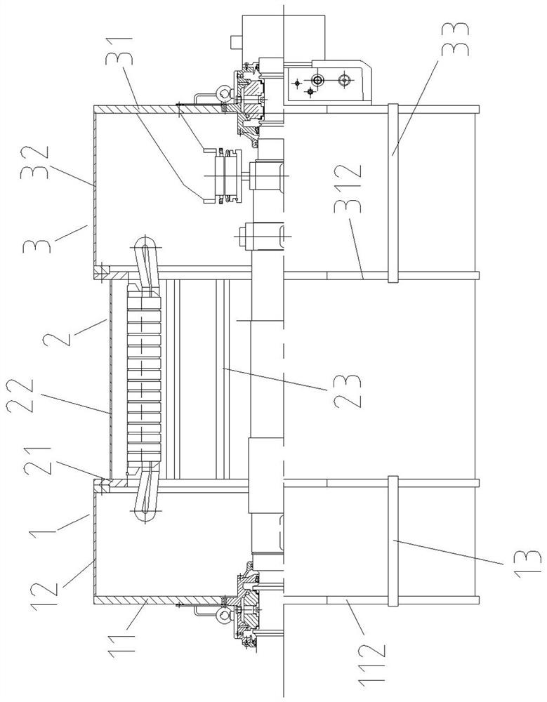
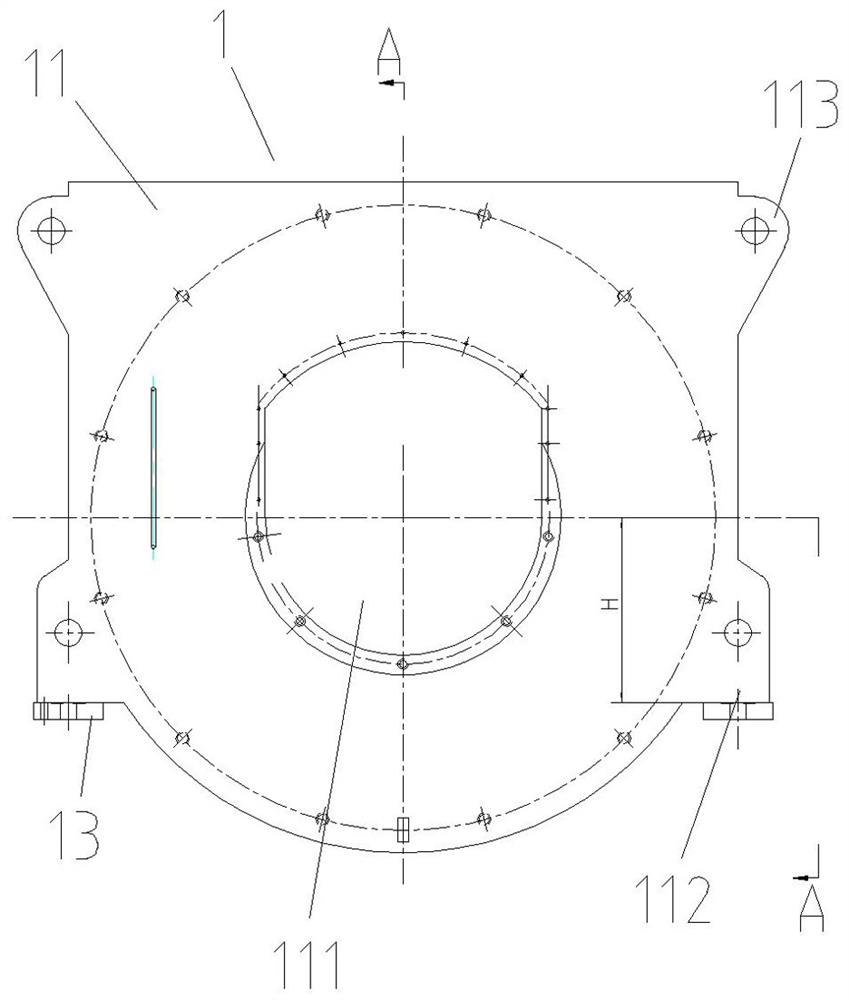
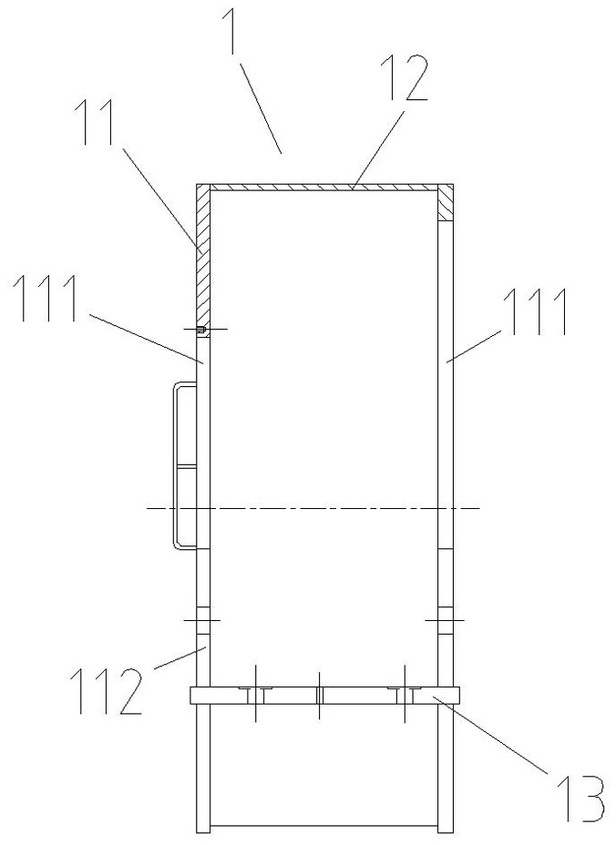
[0046] Such as figure 1 As shown, the present invention includes a front machine base 1, a middle machine base 2 and a rear machine base 3, and the three are sequentially fixed into a whole by fasteners, wherein the front machine base 1 and the rear machine base 3 are square, and the middle machine base Seat 2 is cylindrical. Such as figure 2 and image 3 As shown, the front base 1 includes two front end plates 11, a front housing 12 and two front foot plates 13, and the two front end plates 11 are respectively welded and fixed on the two ends of the front housing 12, and the front end plates 11 of the two The middle part is provided with front mounting hole 111 respectively, and the front mounting hole 111 of outer front end plate 11 is used for in...


PUM


Abstract

The invention discloses a combined synchronous generator base. The combined synchronous generator base comprises a front base, a middle base and a rear base; the front base comprises two front end plates, a front shell and two front bottom foot plates, the two sides of the lower ends of the front end plates extend outwards to form front supporting lug plates respectively, and the two front bottomfoot plates are fixed to the lower sides of the corresponding front supporting lug plates respectively; the middle base comprises two middle end plates and a cylinder, and a plurality of ribs are uniformly and fixedly arranged on the inner wall of the cylinder at intervals; and the rear base comprises two rear end plates, a rear shell and two rear bottom foot plates, the two sides of the lower endof each rear end plate extend outwards to form rear supporting lug plates respectively, and the two rear bottom foot plates are fixed to the lower sides of the corresponding rear supporting lug plates respectively. The combined synchronous generator base is simple in structure and convenient to install, the three bases can be assembled after being machined at the same time, machining can be completed through existing equipment without purchasing large equipment even for a high-power generator, machining is quite convenient, the machining period is short, the cost is greatly saved, and the research and development capacity of a company is improved.

Description

technical field [0001] The invention relates to a generator frame and a processing method thereof, in particular to a split combined generator frame and a processing method thereof, belonging to the technical field of power generation equipment. Background technique [0002] Brushless synchronous generators are widely used in the fields of electric power and new energy, providing power supplies of different power and voltage levels for various equipment loads. The generator is mainly composed of several parts such as the base, the end cover, the stator and the rotor, and the excitation system. The base is the structural part of the entire generator. All have some influence. At present, the machine base is usually of integral structure, but as the power of the generator increases, the size of the machine base increases accordingly, and the size of some machine bases has exceeded the stroke of machining equipment such as boring machines and vertical lathes, resulting in diffi...

Claims


Application Information

Patent Timeline
Patent Type & Authority Applications(China)
IPC IPC(8): H02K5/04H02K15/14
CPCH02K5/04H02K15/14
Inventor 朱明李进赵建华温明亮周鸿波
Owner ZHENJIANG ZHONGCHUAN XIANDAI GENERATING EQUIP CO LTD
Learn More