Single-switch half-bridge electric energy converter

An electric energy converter and single-switch technology, which is applied in the direction of converting the irreversible DC power input into the AC power output with reversible conversion equipment, and can solve the problems of difficult current mode conversion and soft switching control, mutual isolation, and difficulty in Realize problems such as active power factor conversion control and bidirectional power conversion, and achieve the effects of easy current mode conversion and control, low assembly cost, and low cost of mass production.

Pending Publication Date: 2021-02-12
万明武
View PDF0 Cites 1 Cited by
  • Summary
  • Abstract
  • Description
  • Claims
  • Application Information

AI Technical Summary

Problems solved by technology

[0013] The present invention is to solve the problems that existing electric energy converters need to be isolated from each other during complementary driving, it is difficult to realize current-type conversion and soft switch control, and it is difficult to realize active power factor conversion control and bidirectional electric energy conversion. Now, three kinds of single switches are provided. Half Bridge Power Converter

Method used


Image

  • Single-switch half-bridge electric energy converter
  • Single-switch half-bridge electric energy converter
  • Single-switch half-bridge electric energy converter

Examples


specific Embodiment approach 1

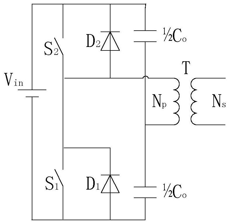
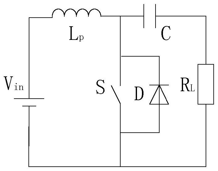
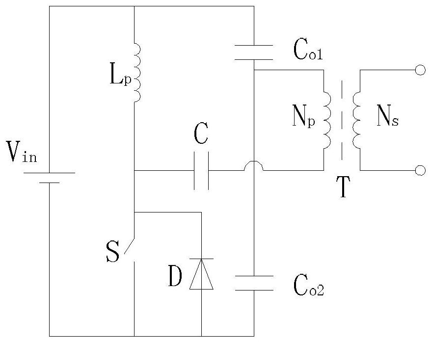
[0041] Specific implementation mode one: refer to image 3 Describe this embodiment in detail, compare figure 1 and figure 2 Two circuit configurations are shown, the figure 1 The capacitive bridge arm in the circuit shown is placed in the figure 2 in the circuit shown, or with figure 2 The inductor L in p replace figure 1 The upper arm switch S in 2 , the connection relationship of other components remains unchanged, and the new circuit structure formed in this way is as follows image 3 As shown, the equivalent circuit of its working principle is as Figure 4 shown. The specific structure is as follows:

[0042] Includes: Inductor L p , capacitance C, capacitance C o1 , capacitance C o2 , switch S, diode D and output transformer,

[0043] One end of the switch S is respectively connected to the negative pole of the DC power supply, the positive pole of the diode D and the capacitor C o2 One end of the switch S and the other end of the switch S are respective...

specific Embodiment approach 2

[0048] Specific implementation mode two: refer to Figure 11 and Figure 12 This embodiment is described in detail. In this embodiment, the lower end of the switch S in the basic conversion unit A is reconnected to one end of the AC input and the input rectifier diode bridge arm at this end is removed; the other end of the AC input is connected to an LC inductor and capacitor input filter. Network; connect the LC capacitor inductance series loop at the original position of the switch S. The specific structure is as Figure 11 As shown, the equivalent circuit of its working principle is as Figure 12 shown.

[0049] Specifically, the single-switch half-bridge power converter described in this embodiment includes: an inductor L i , inductance L p , inductance L R , capacitance C, capacitance C i , capacitance C o , Diode D 1 , Diode D 2 , Diode D 3 , switch S and resistor R LDC ,

[0050] One end of the switch S is respectively connected to one end of the AC power s...

specific Embodiment approach 3

[0057] Specific implementation mode three: refer to Figure 13 Describe this embodiment in detail. The single-switch half-bridge power converter described in this embodiment is characterized in that it includes: an inductor L i , inductance L p , capacitance C b , capacitance C i , capacitance C o1 , capacitance C o2 , Diode D 1 , Diode D 2 , Diode D 3 , switch S, resistor R LAC and resistor R LDC ,

[0058] One end of the switch S is respectively connected to one end of the AC power supply and the capacitor C i One end of the switch S and the other end of the switch S are respectively connected to the inductor L p One end and the capacitor C b at one end, the inductance L i One end is connected to the other end of the AC power supply, the inductance L i Connect the other end of the capacitor C i The other end of the diode D 2 anode and diode D 1 the cathode of the diode D 3 In parallel across the switch S, the diode D 2 The negative poles of the inductors a...


PUM


Abstract

A single-switch half-bridge electric energy converter relates to the field of electric energy converters. The invention aims to solve the problems that the existing electric energy converters need tobe isolated from each other during complementary driving, current type conversion and soft switching control are not easy to realize, and active power factor conversion control and bidirectional electric energy conversion are not easy to realize. One end of a switch S of the single-switch half-bridge electric energy converter is connected with a negative electrode of a direct-current power supply,a positive electrode of a diode D and one end of a capacitor Co2, the other end of the switch S is connected with one end of an inductor Lp, a negative electrode of the diode D and one end of a capacitor C, the other end of the inductor Lp is connected with a positive electrode of the direct-current power supply and one end of a capacitor Co1, the other end of the capacitor Co1 is connected withone end of the output transformer primary and the other end of the capacitor Co2, the other end of the capacitor C is connected with the other end of the output transformer primary, and the output transformer secondary is an alternating current output end.

Description

technical field [0001] The invention belongs to the field of electric energy converters. Background technique [0002] In the field of power converters, the most widely used power converter is a traditional half-bridge power converter composed of a capacitor bridge arm and a switch bridge arm connected to an output circuit, such as figure 1 As shown, this is also the most classic DC / AC power converter. This traditional half-bridge power converter has the following disadvantages: [0003] (1) The switching devices are connected in series up and down in the bridge arm structure, and the connection relationship requires mutual isolation during complementary driving, and the circuit structure is complex and inconvenient to control; [0004] (2) It is not easy to realize current-type conversion; [0005] (3) It is not easy to realize input active power factor control; [0006] (4) In some occasions, there is a hidden danger of the up and down switch through failure. [0007]...

Claims


Application Information

Patent Timeline
Patent Type & Authority Applications(China)
IPC IPC(8): H02M7/48H02M7/72
CPCH02M7/48H02M7/72
Inventor 万明武万博刘彩玲
Owner 万明武
Why Eureka
Try Eureka