Putty powder stirring device for building field

A stirring device and putty powder technology, applied in mixers with rotating stirring devices, transportation, packaging, dissolution, etc., can solve the problems of reducing the progress of painting, small volume of mixing tank, inconvenient moving and placement, etc., to ensure uniform mixing, The device has a compact structure and is easy to move and place

Inactive Publication Date: 2021-02-19
曹传辉
View PDF1 Cites 0 Cited by
  • Summary
  • Abstract
  • Description
  • Claims
  • Application Information

AI Technical Summary

Problems solved by technology

However, the structure of the device is complex. Considering its space ratio, it is inconvenient to move and install the high-rise indoor wall painting. After the stirring shaft and the stirring blade are taken out of the mixing bucket, it is easy to cause the putty powder to drip, which is inconvenient to clean the putty in the mixing bucket. The extraction of powder, and the volume of the mixing tank is small, it is difficult to meet the needs of the construction site, which greatly reduces the painting progress and reduces work efficiency

Method used


Image

  • Putty powder stirring device for building field
  • Putty powder stirring device for building field
  • Putty powder stirring device for building field

Examples


Embodiment 1

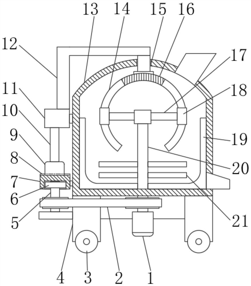
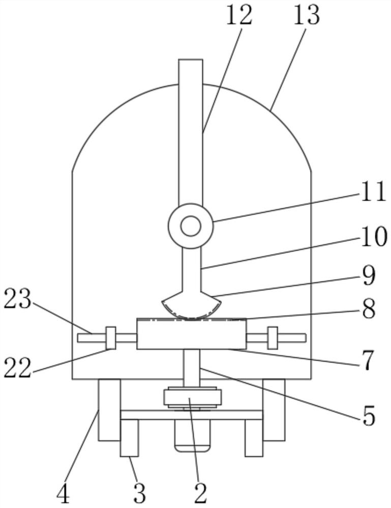
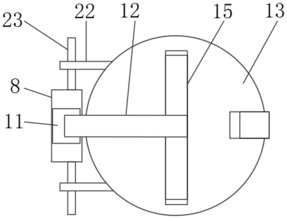
[0026] Embodiment one: refer to Figure 1~4 , in an embodiment of the present invention, a putty powder stirring device for the construction field, including a box body 13, a motor 1 is provided at the outer lower end of the box body 13 to provide a power source, and the output end of the motor 1 is connected to a stirring shaft 20, and the stirring shaft 20 runs through the One end of the box body 13 is evenly provided with a plurality of stirring blades 21 to fully stir and mix the raw materials below the inside of the box body 13. The uppermost end of the stirring shaft 20 is fixedly connected with a bracket 17, and the two ends of the bracket 17 are symmetrically fixedly connected with limited The position block 18, the limit block 18 is moved and connected in the limit groove 14 opened inside the stirring rod 16, so as to realize the movement constraint of the stirring rod 16, and the stirring shaft 20 close to the motor 1 is driven by the belt drive group 2 Connected wit...

Embodiment 2

[0035]Embodiment 2: The invention also provides another embodiment, which is improved on the basis of the above embodiment, and a scraper 19 is fixedly connected to the stirring shaft 20 near the bottom end of the inner wall of the box body 13, The scraper 19 is attached to the inner wall of the box body 13 to clean the inner wall of the box body 13 and prevent the raw materials from adhering to the inner wall of the box body 13 during the stirring process, which wastes materials and is inconvenient for later cleaning.

[0036] In summary, when the invention is working, the raw materials required for the mixing of putty powder and water can be put into the box body 13 through the feed port, the motor 1 is turned on, and under the transmission of the stirring shaft 20, the mixing of the mixing blade 21 to the box body 13 is realized. The raw materials at the bottom of the interior are stirred and mixed, and at the same time through the linkage transmission, the belt drive group ...


PUM


Abstract

The invention discloses a putty powder stirring device for the building field, and relates to the technical field of building construction. The putty powder stirring device comprises a box body, a motor is arranged at the lower end of the exterior of the box body, the output end of the motor is connected with a stirring shaft, a plurality of stirring blades are evenly arranged at the end, penetrating through the box body, of the stirring shaft, the uppermost end of the stirring shaft is fixedly connected with a support, limiting blocks are symmetrically and fixedly connected to the two ends ofthe support, the limiting blocks are movably connected into a limiting groove formed in a stirring rod, a main shaft is in transmission connection with the stirring shaft close to the motor through abelt transmission set, a first sector gear is in key connection with the main shaft, and the first sector gear is in meshing transmission with a rack plate. Through linkage type transmission, combined rotation of the stirring rod is achieved, the stirring blades on the stirring shaft fully mix raw materials in the box body in an up-down all-around mode, and the uniform mixing and stirring qualityof putty powder is guaranteed. The device is compact in structure and convenient to move, the raw material requirement of a construction site is completely met, the construction progress is accelerated, and the working efficiency is improved.

Description

technical field [0001] The invention relates to the technical field of building construction, in particular to a putty powder stirring device for the building field. Background technique [0002] Building construction is a production process that people use various building materials and mechanical equipment to build various building products in a certain space and time according to a specific design blueprint. It includes the entire production process from construction preparation, groundbreaking to project completion acceptance. In this process, construction preparation, construction organization design and management, earthwork engineering, blasting engineering, foundation engineering, steel reinforcement engineering, formwork engineering, scaffolding engineering, concrete engineering, prestressed concrete engineering, masonry engineering, steel structure engineering, and timber structure will be carried out. Engineering, structural installation engineering, etc. The pl...

Claims


Application Information

Patent Timeline
Patent Type & Authority Applications(China)
IPC IPC(8): B01F13/00B01F7/20B01F11/00B01F27/906
CPCB01F27/906B01F31/445B01F33/501B01F2101/48
Inventor 曹传辉
Owner 曹传辉
Why Eureka
Try Eureka