Use method and preparation method of drill bit

A drill bit and drill edge technology, applied in the field of use and preparation of drill bits, can solve the problems of large process dependence, signal integrity bottlenecks and obstacles, and poor control of back drilling depth, so as to get rid of dependence, improve processing efficiency and The effect of machining accuracy

Active Publication Date: 2021-02-19
GUANGDONG DTECH TECH CO LTD
View PDF5 Cites 0 Cited by
  • Summary
  • Abstract
  • Description
  • Claims
  • Application Information

AI Technical Summary

Problems solved by technology

[0002] The Plated Through Hole (PTH) in the multilayer printed circuit board (Printed Circuit Board, PCB) serves as the interconnection function between the inner power layer and the ground layer. When the system enters high-speed signal transmission, the PTH hole will become The bottleneck and obstacle of signal integrity is like an extra "tail" (Stubs) in the transmission line, which acts as a notch filter. In the signal transmission line, when such Stubs appear at two places, a period of oscillation will be formed. Whether it is filtering or oscillation, it will cause damage to high-speed signal transmission and distort the signal
At present, the widely used method is the back-drilling method, but on the one hand, the back-drilling method is highly dependent on the process, and on the other hand, the back-drilling depth is not easy to control

Method used


Image

  • Use method and preparation method of drill bit
  • Use method and preparation method of drill bit
  • Use method and preparation method of drill bit

Examples


Embodiment Construction

[0034] In order to make the technical problems solved by the present invention, the technical solutions adopted and the technical effects achieved clearer, the technical solutions of the embodiments of the present invention will be further described in detail below in conjunction with the accompanying drawings. Obviously, the described embodiments are only the technical solutions of the present invention. Some, but not all, embodiments. Based on the embodiments of the present invention, all other embodiments obtained by those skilled in the art without making creative efforts belong to the protection scope of the present invention.

[0035] In the description of the present invention, unless otherwise clearly specified and limited, the terms "connected", "connected" and "fixed" should be understood in a broad sense, for example, it can be a fixed connection, a detachable connection, or an integrated ; It can be a mechanical connection or an electrical connection; it can be a d...


PUM


Abstract

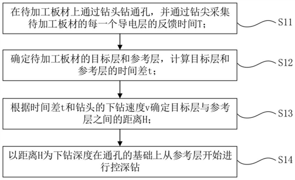
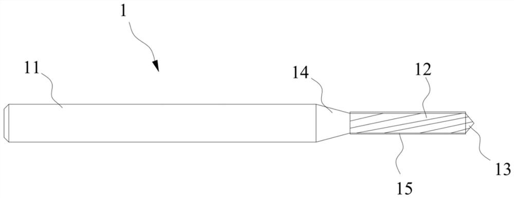
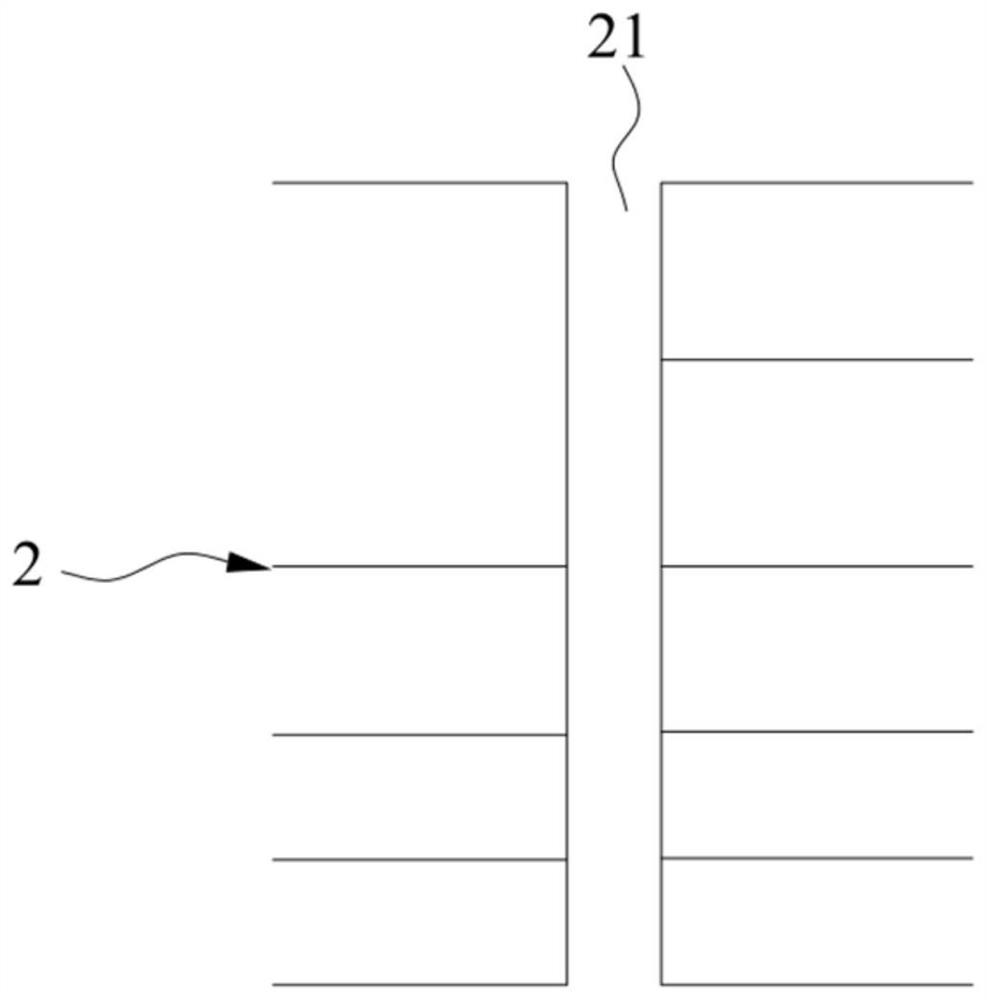
The invention discloses a use method and a preparation method of a drill bit, and relates to the technical field of machining tools. The drill bit comprises a drill handle, a drill blade and a drill tip which are connected in sequence; the drill tip can conduct electricity; and the drill blade is covered with a non-conducting film layer. The use method of the drill bit comprises the following steps that S11, a through hole is drilled in a to-be-machined plate through the drill bit, and the feedback time T of each conducting layer of the to-be-machined plate is collected through the drill tip;S12, a target layer and a reference layer of the to-be-processed plate are determined, and a time difference t between the target layer and the reference layer is calculated; S13, the distance H between the target layer and the reference layer is determined according to the time difference t and the drilling speed v of the drill bit; and S14, the distance H is used as the drilling depth, and depth-controlled drilling is performed from the reference layer on the basis of the through hole. By means of the method, when the drill bit is used for depth-controlled drilling, the drilling depth can beaccurately controlled, meanwhile, the method does not depend on procedures, and the machining efficiency and the machining precision can be improved.

Description

technical field [0001] The invention relates to the technical field of machining tools, in particular to a method for using and preparing a drill bit. Background technique [0002] The Plated Through Hole (PTH) in the multilayer printed circuit board (Printed Circuit Board, PCB) serves as the interconnection function between the inner power layer and the ground layer. When the system enters high-speed signal transmission, the PTH hole will become The bottleneck and obstacle of signal integrity is like an extra "tail" (Stubs) in the transmission line, which acts as a notch filter. In the signal transmission line, when such Stubs appear at two places, a period of oscillation will be formed. Whether it is filtering or oscillation, it will cause damage to high-speed signal transmission and distort the signal. At present, the widely used method is the back drilling method. However, on the one hand, the back drilling method is highly dependent on the process, and on the other han...

Claims


Application Information

Patent Timeline
Patent Type & Authority Applications(China)
IPC IPC(8): B26F1/16B26D5/00B23P15/32
CPCB26F1/16B26D5/00B23P15/32B26F2210/08
Inventor 陈汉泉郑鑫
Owner GUANGDONG DTECH TECH CO LTD
Why Eureka
Try Eureka