Composite-state type motor damping table base

A pedestal and pedestal technology, used in shock absorbers, springs/shock absorbers, shock absorbers, etc., can solve problems such as poor shock absorption effect and equipment impact, reduce the possibility of resonance, ensure stable operation, Good shock absorption effect

Inactive Publication Date: 2021-02-19
夏保友
View PDF0 Cites 0 Cited by
  • Summary
  • Abstract
  • Description
  • Claims
  • Application Information

AI Technical Summary

Problems solved by technology

[0004] The purpose of the present invention is to solve the disadvantages of the traditional shock absorbing pedestal in the prior art that the shock absorbing effect is poor for equipment with a large shock absorbing frequency range, and it may even cause a certain impact on the equipment, and proposes a A Composite Motor Shock Absorbing Base

Method used


Image

  • Composite-state type motor damping table base
  • Composite-state type motor damping table base
  • Composite-state type motor damping table base

Examples


Embodiment 1

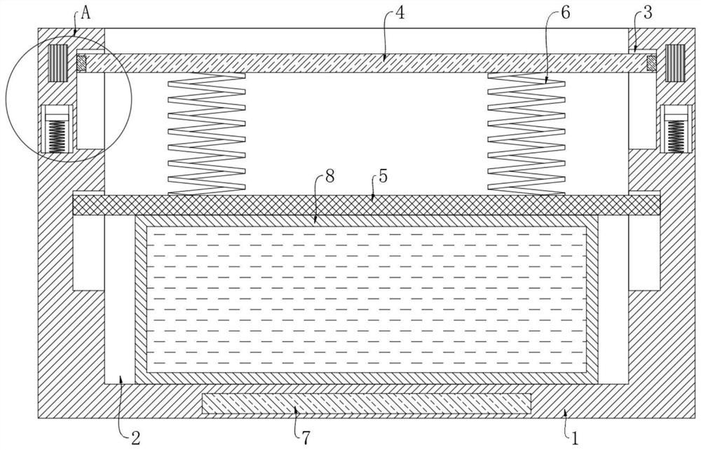
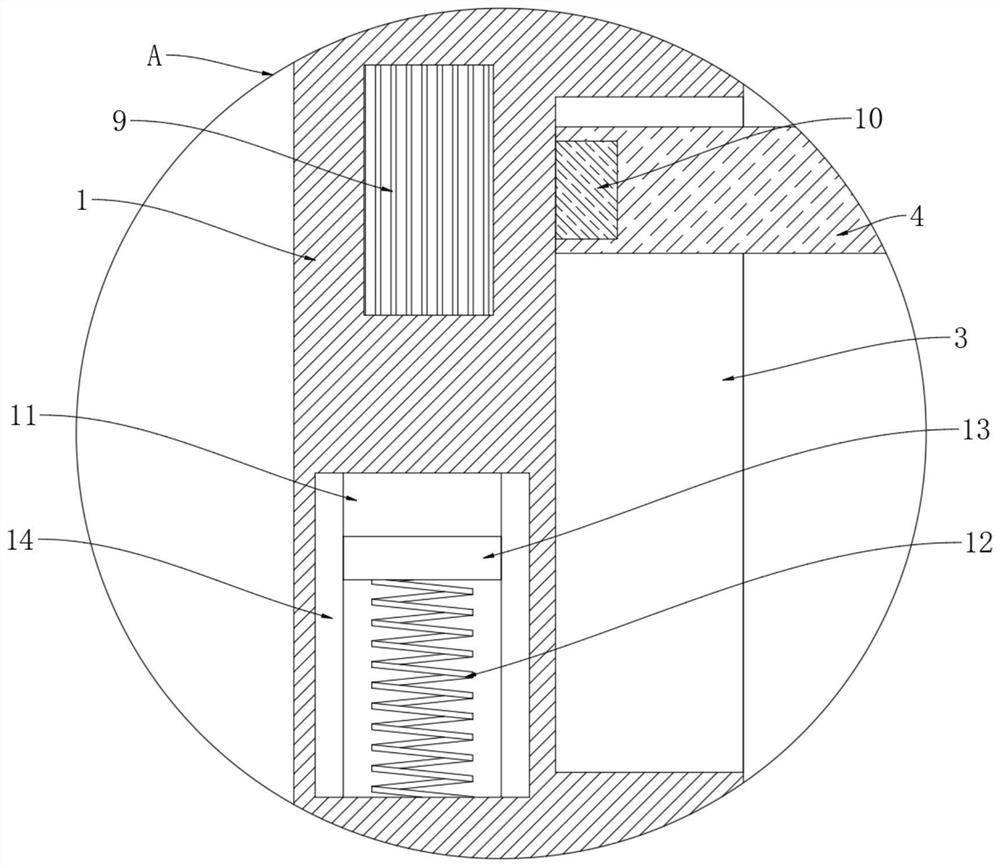
[0017] refer to Figure 1-2 , a composite motor shock-absorbing pedestal, comprising a base 1, the upper end surface of the base 1 is provided with a placement groove 2, and the inner wall of the placement groove 2 is symmetrically provided with a plurality of limiting grooves 3, and the corresponding plurality of limiting grooves The load-bearing plate 4 and the movable plate 5 are slidably connected in 3, and the load-bearing plate 4 is located above the movable plate 5. The load-bearing plate 4 is used to place the working equipment. Spring 6, and the upper and lower ends of a plurality of damping springs 6 are respectively fixedly connected to the lower end surface of the bearing plate 4 and the upper end surface of the movable plate 5, and an elastic airbag is elastically connected between the lower end surface of the movable plate 5 and the bottom groove wall of the placement groove 2 8, and the elastic airbag 8 is filled with magnetorheological fluid (magnetorheological...

Embodiment 2

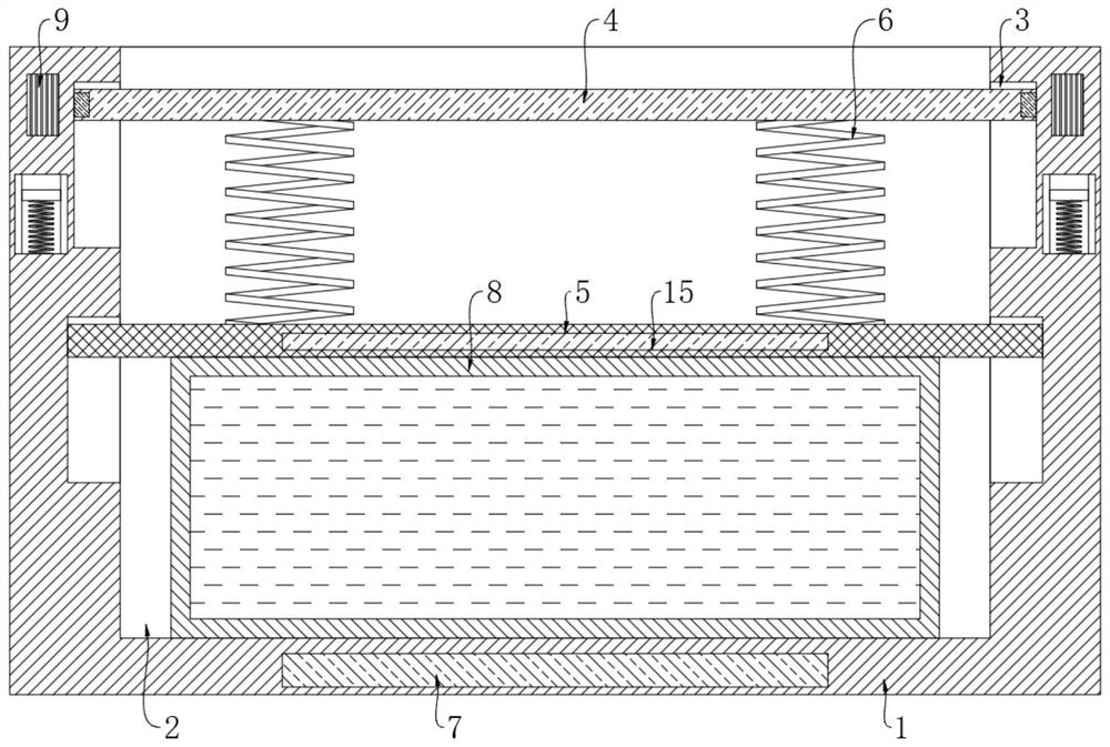
[0022] refer to image 3 The difference between this implementation and Embodiment 1 is that: the lower end surface of the movable plate 5 is provided with a permanent magnet plate 15, and the magnetic pole of the side opposite to the electromagnet 7 of the permanent magnet plate 15 is the same.

[0023] When the magnetic field intensity of the electromagnet 7 changed, the magnetic repulsion between the electromagnet 7 and the permanent magnet plate 15 also changed, and then the compressive force that the shock absorbing spring 6 was subjected to also changed, and then the shock absorbing spring 6, The characteristics of the shock absorber composed of the movable plate 5, the elastic air bag 8 and the magnetorheological fluid can be changed more obviously. For some working equipment with a larger vibration amplitude, the shock absorber effect is more obvious, thereby improving the applicability of the device. sex.


PUM


Abstract

The invention discloses a composite-state type motor damping table base. The composite-state type motor damping table base comprises a base, wherein a placing slot is formed in the upper end surface of the base; a plurality of limiting slots are symmetrically formed in the inner walls of the placing slot; load-bearing plates and movable plates are separately connected in the corresponding limitingslots in a sliding mode; the load-bearing plates are positioned above the movable plates; and a plurality of damping springs are elastically connected between the load-bearing plates and the movableplates. According to the composite-state type motor damping table base disclosed by the invention, a permanent magnet block can be matched with an induction coil, so that magnetic field intensity of an electromagnet can change along with changes of vibrating frequency of working equipment, and thus, the purpose of adjusting an applicable frequency range according to changes of vibrating frequencyof the working equipment by a damping part consisting of damping springs, the movable plates, elastic gasbags and magnetorheological fluid is achieved, the working equipment can be damped and bufferedbetter, resonance possibility of the base and working equipment further can be reduced, and the working equipment can be guaranteed to stably operate.

Description

technical field [0001] The invention relates to the technical field of shock absorbing equipment, in particular to a composite motor shock absorbing pedestal. Background technique [0002] When equipment such as motors, generators, compressors, and fans work, they often generate large vibrations. Therefore, special shock-absorbing pedestals are required. Traditional shock-absorbing pedestals are often composed of multiple shock-absorbing springs. Although they can It has a certain buffering effect on the vibration of these devices, but because the power of these devices is fluctuating when they work, the resulting vibration frequency also changes accordingly. However, the traditional shock-absorbing pedestal has The shock absorption frequency range is fixed, so the shock absorption effect is not good during use, and even when the vibration of the equipment changes, it will resonate with the shock absorption base, which will not only affect the normal use of the equipment, bu...

Claims


Application Information

Patent Timeline
Patent Type & Authority Applications(China)
IPC IPC(8): F16F3/07H02K5/24
CPCF16F13/007F16F2222/06H02K5/24
Inventor 夏保友肖群
Owner 夏保友
Why Eureka
Try Eureka