Plate impact test device

An impact test and plate technology, which is applied in measuring devices, analytical materials, instruments, etc., to achieve the effect of effective and reliable experimental data and simple and easy methods

Active Publication Date: 2021-02-19
HENAN UNIVERSITY +1
View PDF10 Cites 3 Cited by
  • Summary
  • Abstract
  • Description
  • Claims
  • Application Information

AI Technical Summary

Problems solved by technology

[0007] Aiming at the defects and problems existing in the existing impact test devices used in plate testing, the present invention provides a plate impact test device, which is used to achieve fast and better plate and impact heads, and achieve accurate test results, suitable for short-term realization batch test

Method used


Image

  • Plate impact test device
  • Plate impact test device
  • Plate impact test device

Examples


Embodiment 1

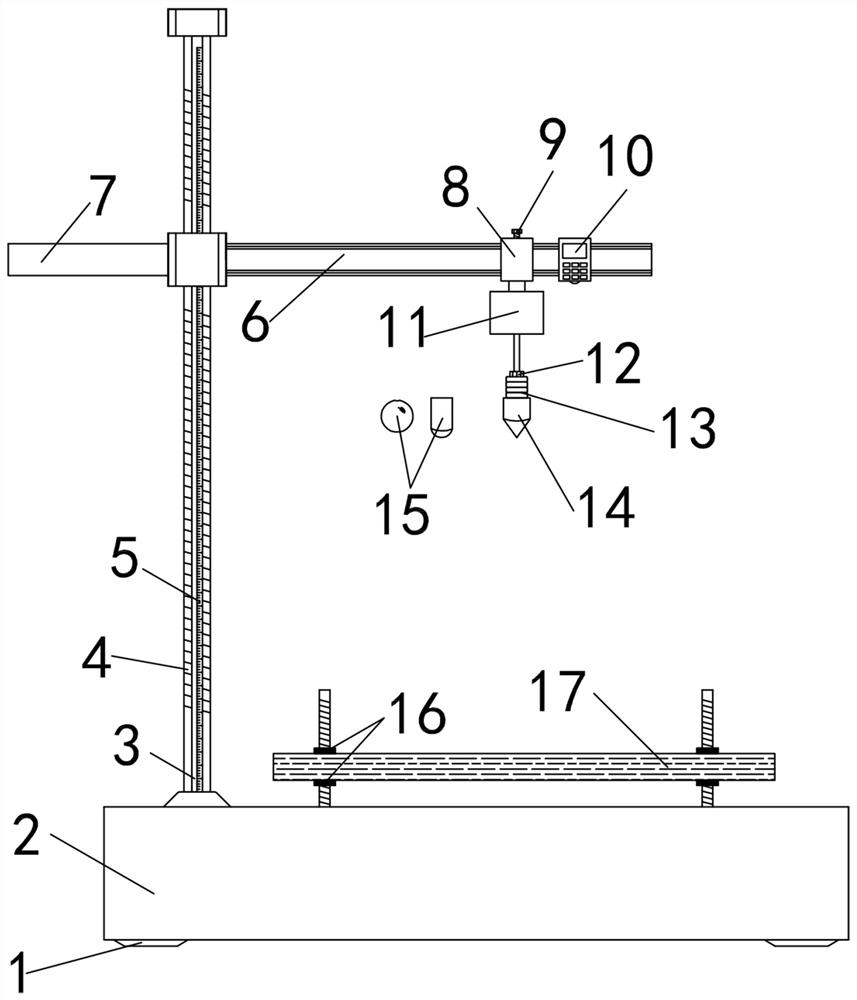
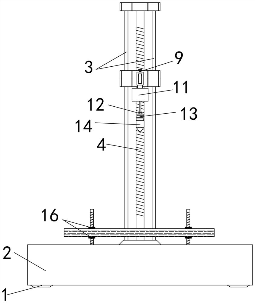
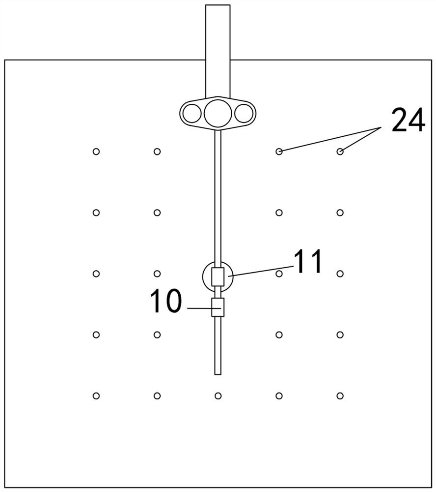
[0034] Embodiment 1: This embodiment provides a plate impact test device, including an improved structure for quick replacement of various impact hammers. Figure 1-Figure 3 A simplified structural diagram of the experimental setup is shown, Figure 4 The assembly relationship of the impact head clamping assembly is shown.

[0035] from figure 1 It can be seen that the experimental device mainly includes a fixed foot support 1, a base 2, a limit rod 3, a transmission shaft 4, a height gauge 5, a liftable horizontal rod 6, a horizontal counterweight rod 7, a horizontal adjustment bracket 8, a fastening Screw 9, laser rangefinder 10, magnetic fixture 11, etc. Specifically, the fixed legs 1 are located at the four top corners below the base to support the base 2, and the left side of the base 2 (such as figure 1 ) is erected and fixed with double parallel limit rods 3 (such as figure 2 ), there is a transmission shaft 4 vertically fixed on the upper part of the base 2 betwee...

Embodiment 2

[0042] Embodiment 2: improve on the basis of embodiment 1, adopt such as figure 2 In the plate impact test device shown, a sliding sleeve is also installed on the slider, and the lifting horizontal rod 6 is fixed on one side of the sliding sleeve, so that the sliding sleeve can move longitudinally along the sliding block, and then drive the lifting horizontal rod 6 together. Pan vertically. This design can not only fix the liftable horizontal bar 6 and the sliding sleeve at the center position of the slider, which has the same effect as that of embodiment 1, but also can change the longitudinal position of the liftable horizontal bar 6 so that other parts of the plate to be tested location to test.

Embodiment 3

[0043] Embodiment 3: On the basis of Embodiment 1 or 2, a diamond-shaped body 41 is fixed on the upper end of the central combination rod, such as Figure 13 As shown, at the same time, a Y-shaped oblique slideway 39 is provided at the center of the body of the magnetic fixture 11, and the oblique slider 40 is matched therein. When the oblique sliders 40 on both sides lose their magnetism, they slide down and are supported on the The lower slopes on both sides of the rhombus 41, when both sides are inclined to the slide block 40 after being magnetized, slide upwards and break away from the lower slopes on both sides of the rhombus 41 to make the central combination rod and the impact head clamping assembly assembly fall down.


PUM


Abstract

The invention discloses a plate impact testing device. Double parallel limiting rods are vertically fixed to one side of a base, a transmission shaft vertically fixed to the upper portion of the baseis located between the double parallel limiting rods, the transmission shaft is in transmission connection with a driving mechanism and can rotate, and a sliding block is in threaded connection with the outer side of the transmission shaft. The two sides of each sliding block are arranged on the outer sides of the corresponding limiting rods in a sleeving mode through guide holes, a liftable horizontal rod is fixed to the inward side wall of each sliding block, the outer side of each liftable horizontal rod is sleeved with a horizontal adjusting support capable of horizontally sliding and being locked, and a magnetic attraction clamp is fixed to the lower end of each horizontal adjusting support. An impact head clamping assembly is attracted to the lower portion of the magnetic attractionclamp through electromagnetism. According to the invention, multiple drop hammer impact tests of different impact hammers can be realized, and the auxiliary guide mechanism for the impact head clamping assembly is arranged for preventing the problem that the impact hammers are easy to deflect due to the possible influence of lateral force and friction force in the process of separating each impactcone from the magnetic attraction fixture.

Description

technical field [0001] The invention belongs to impact test tools in the field of civil engineering, in particular to a board impact test device. Background technique [0002] Impact test is generally a set of test methods to determine the safety, reliability and durability of composite materials, metals, plastics, film materials, pipes, etc. when they are subjected to external impact. [0003] Panels are an important part of civil and industrial buildings. With the advancement of technology, various new, composite, energy-saving, green and other panels emerge in an endless stream and are used in actual production and life. There are also many problems that need to be solved urgently. [0004] At present, in the process of testing the mechanical properties of composite materials, it is essential to test the impact resistance of composite materials. Composite materials have a series of advantages such as high specific strength, high specific modulus, good fatigue resistance...

Claims


Application Information

Patent Timeline
Patent Type & Authority Applications(China)
IPC IPC(8): G01N3/303G01N3/04
CPCG01N3/303G01N3/04G01N2203/001G01N2203/0039G01N2203/0423
Inventor 马少春陈龙鲁冰李娜娜鲍鹏王辉
Owner HENAN UNIVERSITY
Why Eureka
Try Eureka