Direct-current cable for rail transit

A DC cable and rail transit technology, applied in the direction of insulated cables, flexible cables, cable/conductor manufacturing, etc., can solve the problem of increasing the time required for DC cables for rail transit, reducing the waterproof effect of DC cables for rail transit, and reducing the track Problems such as processing efficiency of DC cables for transportation, to avoid water short circuit, improve waterproof effect, and good bending effect

Active Publication Date: 2021-02-19
新亚特电缆股份有限公司
View PDF14 Cites 0 Cited by
  • Summary
  • Abstract
  • Description
  • Claims
  • Application Information

AI Technical Summary

Problems solved by technology

[0004] In order to overcome the fact that the traditional DC cables for rail transit do not have multiple protection structures, when the traditional DC cables for rail transit are laid at corners, they are easily affected by stress and cracks, thereby reducing the use of DC cables for rail transit. Stability, at the same time, traditional rail transit DC cables cannot be soaked in water for a long time, and traditional rail transit DC cables themselves do not have a waterproof layer, which reduces the waterproof effect of rail transit DC cables; secondly, traditional rail transit DC cables are used in During the extrusion operation, it is necessary to cool the extruded cable structure, which increases the time required for the extrusion operation of the DC cable for rail transit and reduces the processing efficiency of the DC cable for rail transit; at the same time, the traditional rail When the DC cable for transportation is extruding and processing the sheath, the sheath material is likely to be blocked during the transportation process, which interrupts the processing of the DC cable for the traditional rail transit and reduces the production time of the DC cable for the traditional rail transit. stability, and provide a DC cable for rail transit

Method used


Image

  • Direct-current cable for rail transit
  • Direct-current cable for rail transit
  • Direct-current cable for rail transit

Examples


Embodiment Construction

[0032] The technical solutions in the embodiments of the present invention will be clearly and completely described below in conjunction with the embodiments of the present invention. Apparently, the described embodiments are only some of the embodiments of the present invention, not all of them. Based on the embodiments of the present invention, all other embodiments obtained by persons of ordinary skill in the art without creative efforts fall within the protection scope of the present invention.

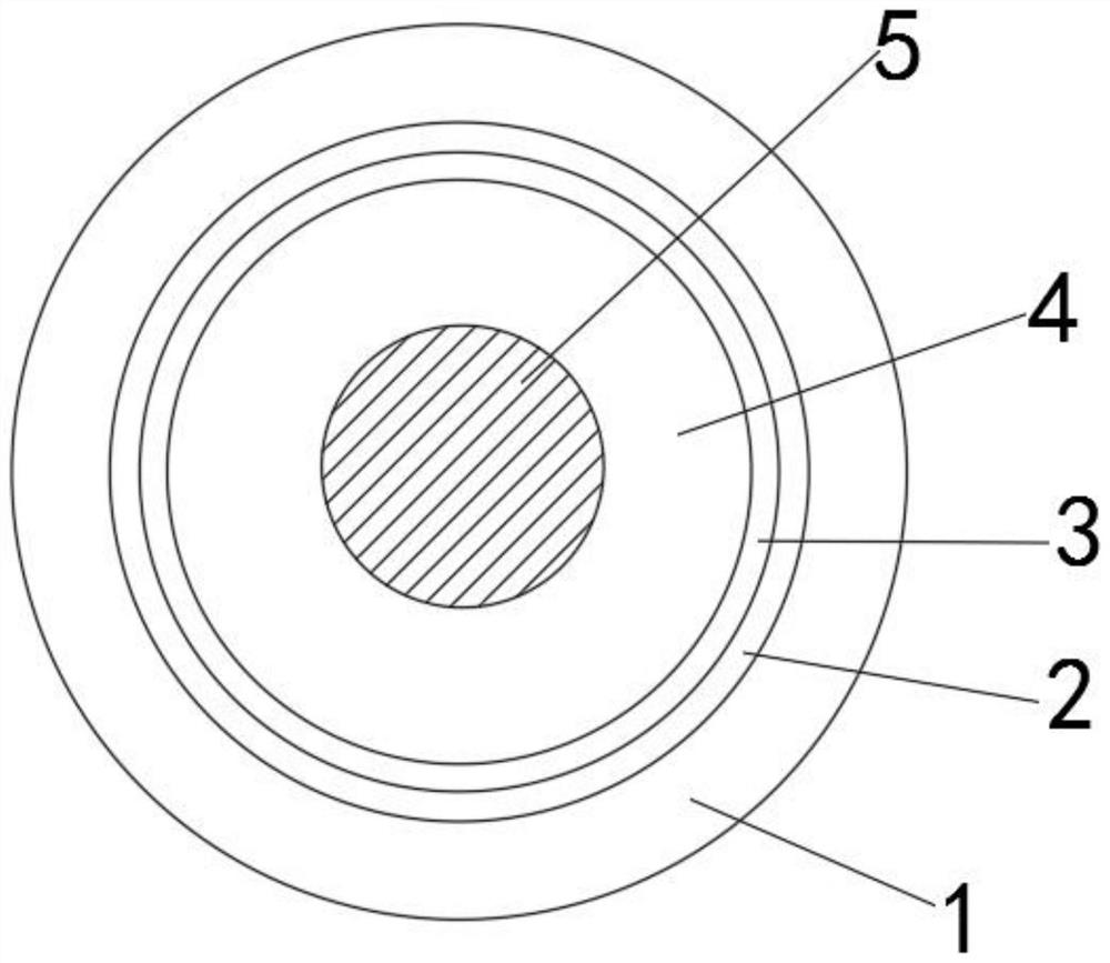
[0033] Such as Figure 1-5 As shown, a DC cable for rail transit includes a sheath layer 1, a flame-retardant layer 2 and a water-blocking layer 3, an insulator 4 and a conductor 5, the insulator 4 is wrapped on the outer surface of the conductor 5, and the side outer surface of the insulator 4 is set There is a water-blocking layer 3, the outer surface of the water-blocking layer 3 is wound with a water-blocking layer 3, the outer surface of the side of the water-blocking layer 3...


PUM


Abstract

The invention discloses a direct-current cable for rail transit, which comprises a sheath layer, a flame retardant layer, a water blocking layer, an insulator and a conductor, the insulator wraps theouter surface of the conductor, the water blocking layer is arranged on the outer surface of the side edge of the insulator, the flame retardant layer is wound on the outer surface of the water blocking layer, and the sheath layer is extruded on the outer surface of the side edge of the water blocking layer. The insulator is arranged between the conductor and the water-blocking layer, and the flame-retardant layer is arranged between the water-blocking layer and the sheath layer. According to the direct-current cable for rail transit, the direct-current cable for rail transit has a multi-protection structure, the bending effect of the direct-current cable for rail transit is improved, the cracking phenomenon of the direct-current cable for rail transit during bending laying is avoided, andmeanwhile, the waterproof effect of the direct-current cable for rail transit is improved; and therefore, the direct-current cable can be used underwater for a long time, and the safety of the direct-current cable in use is improved.

Description

technical field [0001] The invention belongs to the technical field of cables, in particular to a DC cable for rail transit. Background technique [0002] The cable is usually a rope-like cable twisted by several or several groups of wires (at least two in each group). Each group of wires is insulated from each other and is often twisted around a center. Insulated covering layer, the cable has the characteristics of internal electrification and external insulation. [0003] The existing DC cables for rail transit have certain disadvantages in the use process. The traditional DC cables for rail transit do not have multiple protection structures, so that the traditional DC cables for rail transit are easily affected by stress when they are laid at corners. Cracking occurs, which reduces the stability of DC cables for rail transit. At the same time, traditional DC cables for rail transit cannot be used in water for a long time. Traditional DC cables for rail transit do not hav...

Claims


Application Information

Patent Timeline
Patent Type & Authority Applications(China)
IPC IPC(8): H01B7/02H01B7/04H01B7/282H01B7/288H01B7/295H01B3/28H01B13/00H01B13/22H01B13/24B65H54/54
CPCH01B7/02H01B3/28H01B7/2825H01B7/282H01B7/295H01B7/288H01B7/04H01B13/0036H01B13/228H01B13/24B65H54/54Y02A30/14
Inventor 韩惠福朱崤周光亚陈文龙彭建锋李兵朱强中王敏叶松林雷俊霞顾倩倩
Owner 新亚特电缆股份有限公司
Why Eureka
Try Eureka