Waste gas trapping and purifying device for activated carbon adsorption tower

A technology of activated carbon adsorption tower and purification device, which is applied in the direction of gas treatment, chemical instruments and methods, and dispersed particle filtration, etc., which can solve the problems of large damage to activated carbon, time-consuming and labor-consuming, and damage to activated carbon, so as to improve the flow rate of exhaust gas and achieve better filtration Environment, the effect of increasing the cooling rate

Active Publication Date: 2021-02-23
淄博华岳环保设备有限公司
View PDF9 Cites 3 Cited by
  • Summary
  • Abstract
  • Description
  • Claims
  • Application Information

AI Technical Summary

Problems solved by technology

[0003] However, the adsorption efficiency of the activated carbon adsorption tower will be affected by the flow rate and temperature of the exhaust gas. If the temperature is too high, the activated carbon will be damaged. If the flow rate is too fast, the activated carbon will not have enough time to absorb harmful gases. The particles in the exhaust gas will block the pores of the activated carbon. Weaken the adsorption effect of activated carbon. The existing exhaust gas cooling equipment often uses water mist to cool down, but the water will be transferred to the activated carbon adsorption tower and absorbed by the activated carbon, which will weaken the adsorption effect of activated carbon. At the same time, activated carbon has adsorption saturation. After a period of time, the internal activated carbon needs to be replaced, which is time-consuming and labor-intensive, and the continuous replacement of activated carbon requires a lot of cost. However, the existing activated carbon regeneration often uses a regeneration method that damages the activated carbon in a hurry, which is not conducive to the recycling of activated carbon.

Method used


Image

  • Waste gas trapping and purifying device for activated carbon adsorption tower
  • Waste gas trapping and purifying device for activated carbon adsorption tower
  • Waste gas trapping and purifying device for activated carbon adsorption tower

Examples


Embodiment Construction

[0035] The following will clearly and completely describe the technical solutions in the embodiments of the present invention with reference to the accompanying drawings in the embodiments of the present invention. Obviously, the described embodiments are only some, not all, embodiments of the present invention. Based on the embodiments of the present invention, all other embodiments obtained by persons of ordinary skill in the art without making creative efforts belong to the protection scope of the present invention.

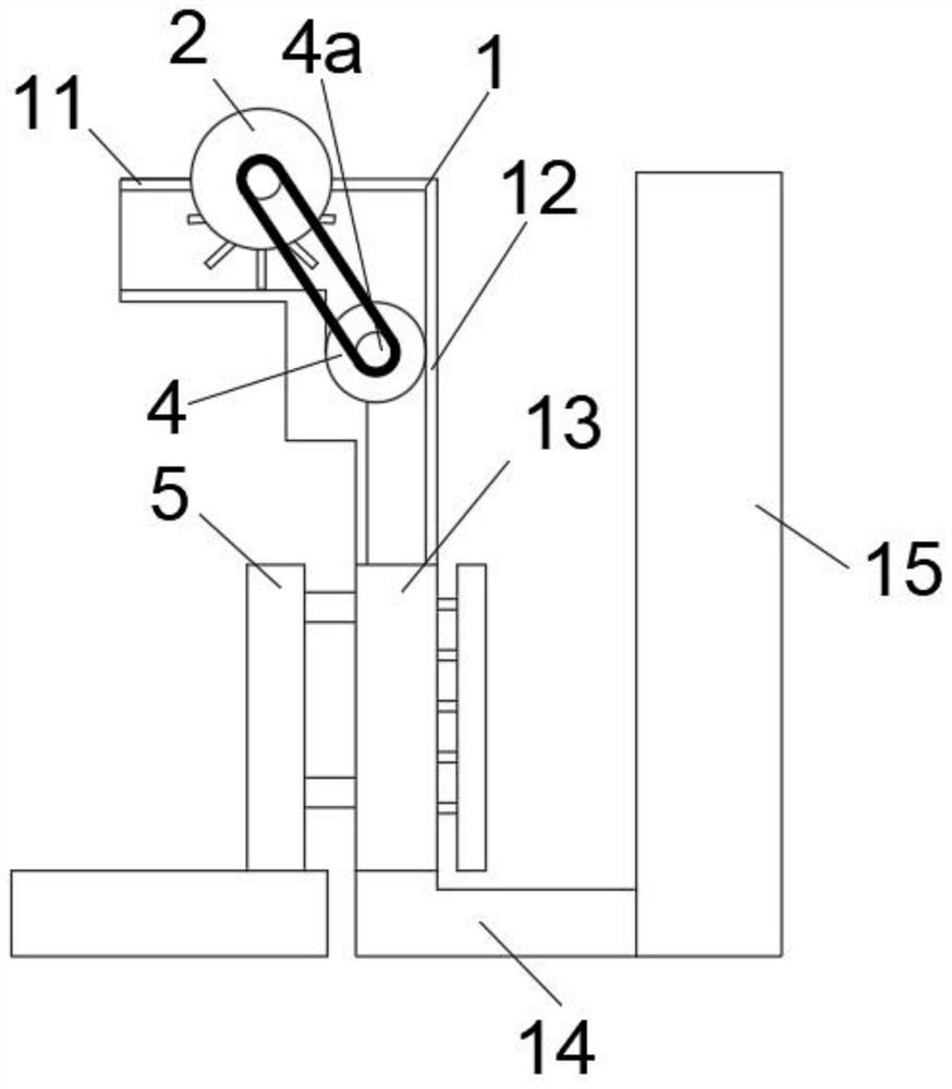
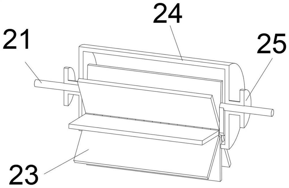
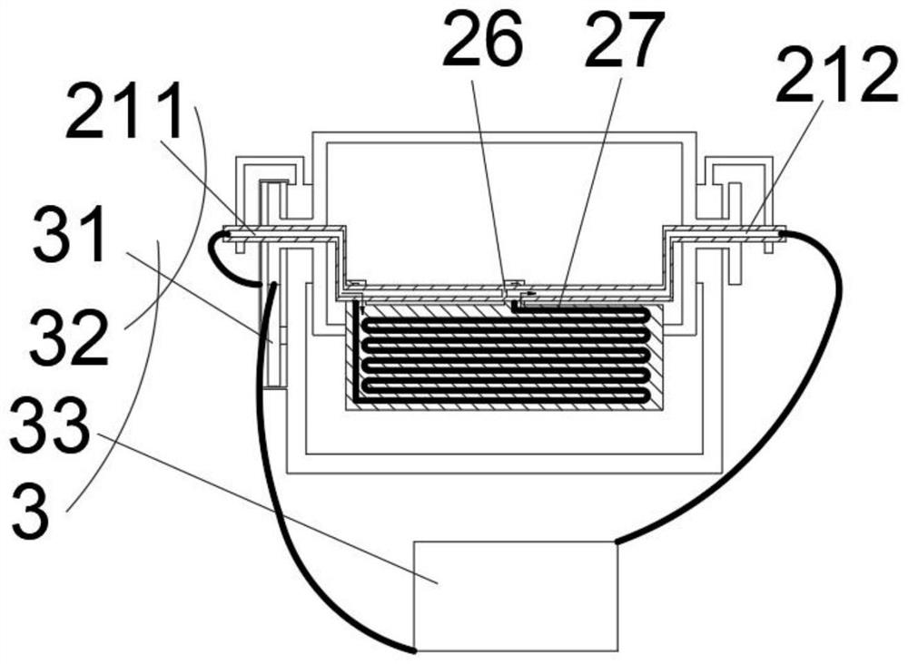
[0036] see Figure 1-10 , the present invention provides a technical solution: as figure 1 , an exhaust gas collection and purification device for activated carbon adsorption towers, including a waste channel 1, a flow rate control component 2 is installed at one end of the waste channel 1, a cooling component 3 is installed inside the flow rate control component 2, and a flow rate control component 2 is installed below the component Filter assembly 4, regene...


PUM


Abstract

The invention discloses a waste gas trapping and purifying device for an activated carbon adsorption tower. The waste gas trapping and purifying device comprises a waste channel, the waste channel comprises an air inlet pipe, the air inlet pipe is transversely installed, a flow speed control assembly is arranged at the upper end of the air inlet pipe, and a cooling assembly is arranged in the flowspeed control assembly; and a vertically-installed filter pipe is arranged at the tail end of the air inlet pipe, a filter assembly is arranged at the top end of the filter pipe, an activated carbonpipe is arranged on the lower side of the filter pipe, a regeneration assembly is arranged on the lower side of the activated carbon pipe, a discharge pipe is arranged on the lower side of the activated carbon pipe, and a discharge tower is arranged at the end of the discharge pipe. The device has the characteristics that the flow velocity and temperature of waste gas can be controlled, the moisture of the waste gas cannot be increased, particles can be filtered out, and activated carbon can be regenerated and recycled.

Description

technical field [0001] The invention relates to the technical field of industrial machinery, in particular to a waste gas collection and purification device used in an activated carbon adsorption tower. Background technique [0002] Activated carbon adsorption tower is the best purification equipment for organic waste gas and odor treatment. Activated carbon adsorption is an effective measure to remove water odor, natural and synthetic dissolved organic matter, micro-pollutants, etc. Most of the relatively large organic molecules, aromatic compounds, halogenated alkynes, etc. can be firmly adsorbed on the surface or in the void of activated carbon, and have obvious removal effects on humus, synthetic organic matter and low molecular weight organic matter. Activated carbon adsorption is used as a deep purification process , often used in the final treatment of wastewater, and can also be used in the purification of long-term production water and domestic water. [0003] How...

Claims


Application Information

Patent Timeline
Patent Type & Authority Applications(China)
IPC IPC(8): B01D53/04B01D46/12B01D46/42
CPCB01D53/0454B01D46/0056B01D2253/102B01D46/00B01D53/0407B01D53/0446B01D46/2411B01D2257/80B01D2258/02Y02C20/40
Inventor 不公告发明人
Owner 淄博华岳环保设备有限公司
Why Eureka
Try Eureka