Width-adjustable belt sander

A sander and width adjustment technology, which is applied in the field of sander, can solve the problems that the width of the grinding wheel cannot be adjusted, there is no sliding guide structure on both sides, and the scope of application is reduced.

Inactive Publication Date: 2021-02-23
嘉善康达自动化机械股份有限公司
View PDF0 Cites 4 Cited by
  • Summary
  • Abstract
  • Description
  • Claims
  • Application Information

AI Technical Summary

Problems solved by technology

[0002] At present, a sander, also known as a sander, is one of the equipment commonly used in the modern wood processing industry. It uses a cutting tool equipped with abrasives (abrasive cloth or sandpaper) to sand the workpiece to improve its thickness accuracy, plane Sanding machine is widely used in all kinds of man-made For the finishing of plates, wood products and woodware, sanding machines can not only process planes, but also process outer and inner circles, arcs and molding surfaces. Sanding machines can not only be used for processing the base surface to be painted, It is also used for sanding and polishing of paint coatings, so sanding machines are one of the necessary equipment for wood products processing in enterprises such as wood, furniture, vehicles, ships, construction, military industry, wooden molds, and wooden toys. The synonym refers to the physical removal of some materials and obje

Method used


Image

  • Width-adjustable belt sander
  • Width-adjustable belt sander
  • Width-adjustable belt sander

Examples


Example Embodiment

[0024]In order to make the objectives, technical solutions and advantages of the present invention, the present invention will be described in further detail below with reference to the accompanying drawings and examples. It should be understood that the specific embodiments described herein are merely intended to illustrate the invention and are not intended to limit the invention.

[0025]In the description of the present invention, it is to be noted that the term "center", "upper", "lower", "left", "right", "front", "post", "vertical", "horizontal", The orientation or positional relationship of "inside", "outside", etc. is based on the orientation or positional relationship shown in the drawings, which is merely described in the present invention and simplified description, rather than indicating or implying that the device or component must have The specific orientation is constructed and operated in a specific orientation, so it is not understood to limit the invention. Moreover, ...


PUM


Abstract

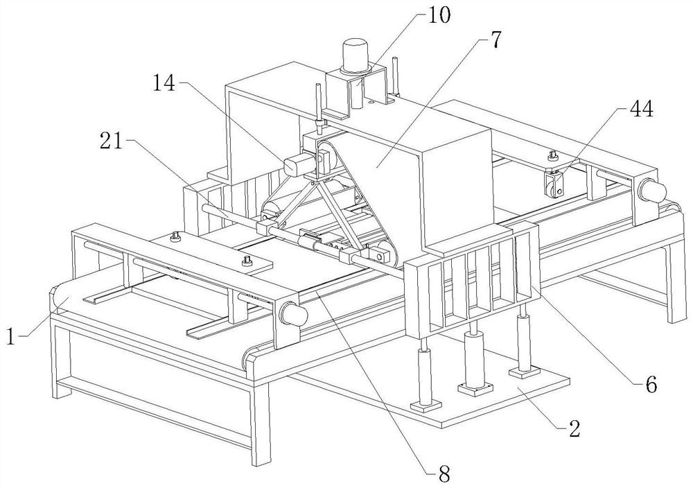
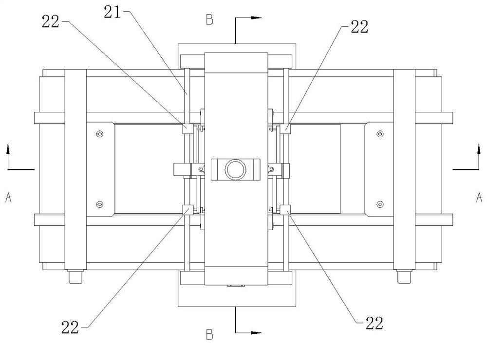
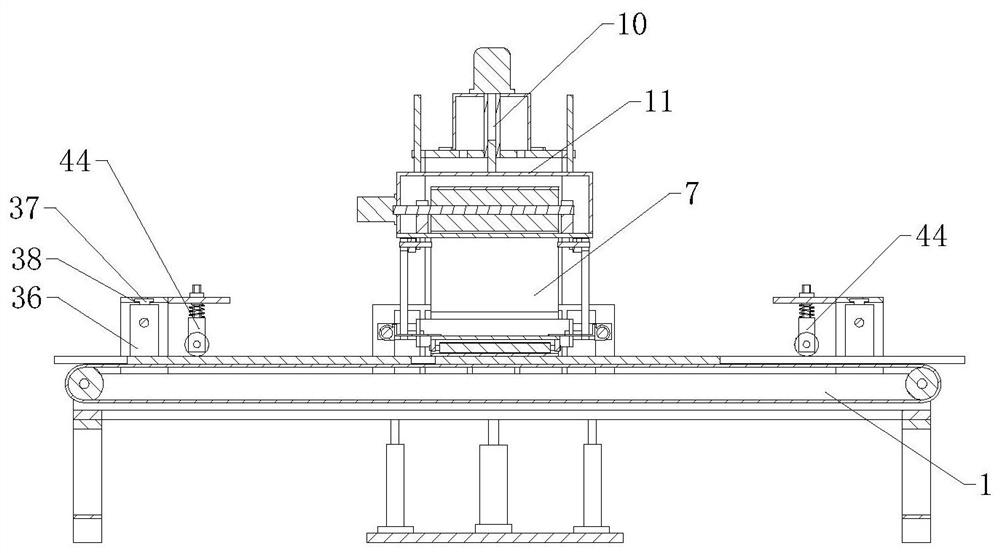
The invention relates to the technical field of sanders, in particular to a width-adjustable belt sander. The width-adjustable belt sander comprises a feeding conveyor, a bottom plate erected below the feeding conveyor, a width adjusting sanding assembly, two positioning driving assemblies and two lifting assemblies, wherein the two lifting assemblies are symmetrically located on the two sides ofthe feeding conveyor, the two lifting assemblies are installed at the two ends of the bottom plate, each lifting assembly comprises a lifting vertical support, the width adjusting sanding assembly isarranged between the two lifting vertical supports, the width adjusting sanding assembly comprises a polishing abrasive belt distributed in the width direction of the feeding conveyor, positioning guide plates are arranged on the two sides of the upper portion of the feeding conveyor, the two positioning driving assemblies are symmetrically arranged at the two ends of the feeding conveyor, and theworking ends of the two positioning driving assemblies are connected with the two ends of each positioning guide plate. The equipment is provided with two plate positioning structures used for positioning and guiding plates, the length of the polishing abrasive belt can be automatically adjusted according to the width of the plates, and the machining applicability is improved.

Description

technical field [0001] The invention relates to the technical field of sanding machines, in particular to a belt sanding machine with adjustable width. Background technique [0002] At present, a sander, also known as a sander, is one of the equipment commonly used in the modern wood processing industry. It uses a cutting tool equipped with abrasives (abrasive cloth or sandpaper) to sand the workpiece to improve its thickness accuracy, plane Sanding machine is widely used in all kinds of man-made For the finishing of plates, wood products and woodware, sanding machines can not only process planes, but also process outer and inner circles, arcs and molding surfaces. Sanding machines can not only be used for processing the base surface to be painted, It is also used for sanding and polishing of paint coatings, so sanding machines are one of the necessary equipment for wood products processing in enterprises such as wood, furniture, vehicles, ships, construction, military indu...

Claims


Application Information

Patent Timeline
IPC IPC(8): B24B21/04B24B21/18B24B41/00
CPCB24B21/04B24B21/18B24B41/005
Inventor 钱国平
Owner 嘉善康达自动化机械股份有限公司
Why Eureka
Try Eureka