
Ultrasonic vibration combined type well washing device and well washing method

An ultrasonic and composite technology, applied in wellbore/well components, vibration generating devices, wellbore/well valve devices, etc., can solve the problems of flowback fluid falling, low well cleaning efficiency, and incomplete scale removal.

Active Publication Date: 2021-02-23
NO 1 SURVEYING TEAM OF ANHUI CHARCOAL FIELD & GEOLOGY BUREAU +1
View PDF12 Cites 3 Cited by
  • Summary
  • Abstract
  • Description
  • Claims
  • Application Information

AI Technical Summary

Problems solved by technology

[0004] At present, in order to remove the scaling in the well, Chinese patent CN109538163A discloses a kind of ultrasonic vibration compound type well cleaning device and well cleaning method, including a power box, a power line, a drill pipe, a second water passage, a connecting rod, a second Rod, ultrasonic vibrator, first rod, bottom plate, spring (and pressure plate, in the process of use, because the piston is used to block the formed channel, if the piston is fixedly connected with the filter and the drill pipe , the efficiency of pumping is affected during evacuation. If the drill rod and piston are lowered during use, the piston can move up and down, and the sealing effect is poor during sealing. When the liquid is back-drained, it is easy to fall back. , resulting in unsatisfactory flowback. At the same time, when the ultrasonic vibrator is in contact with the filter, the contact stability is poor. When the vibration descaling is performed, the descaling is not complete, and the ultrasonic vibrator is easy to In the case of falling off, the efficiency of well cleaning is low. When evacuating at the same time, the evacuation efficiency is relatively reduced due to the existence of the piston, which affects the recovery of heat in the geothermal well.

Method used


Image

  • Ultrasonic vibration combined type well washing device and well washing method
  • Ultrasonic vibration combined type well washing device and well washing method
  • Ultrasonic vibration combined type well washing device and well washing method

Examples


Embodiment 1

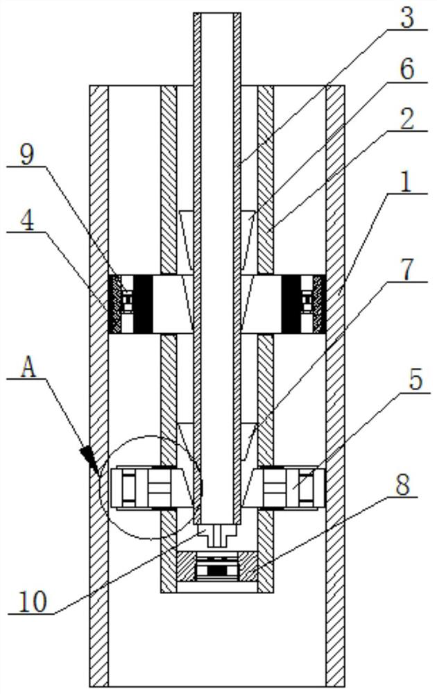
[0053] Such as figure 1 The ultrasonic vibration composite well cleaning device includes an inner casing 2 arranged in the liquid return pipe 1 in the well, a well flushing pipe 3 arranged in the inner casing 2 and extending to the outside of the liquid return pipe 1 ;

[0054] The liquid return pipe 1 is lowered into a water supply well or a geothermal well for collecting hot water in the well, and the inner casing 2 is the base pipe of a composite well cleaning device, which is lowered during well cleaning to avoid affecting the production process. When it is hot, the efficiency of heat extraction is reduced; the well-flushing pipe is used to inject well-flushing fluid into the hot liquid pipe to clean the liquid return pipe;

[0055] The upper part of the inner casing 2 is covered with a packer assembly 4, and the end of the packer assembly 4 connected to the inner casing 2 extends into the inner casing 2; Liquid through holes 405, each liquid return through hole 405 is p...

Embodiment 2

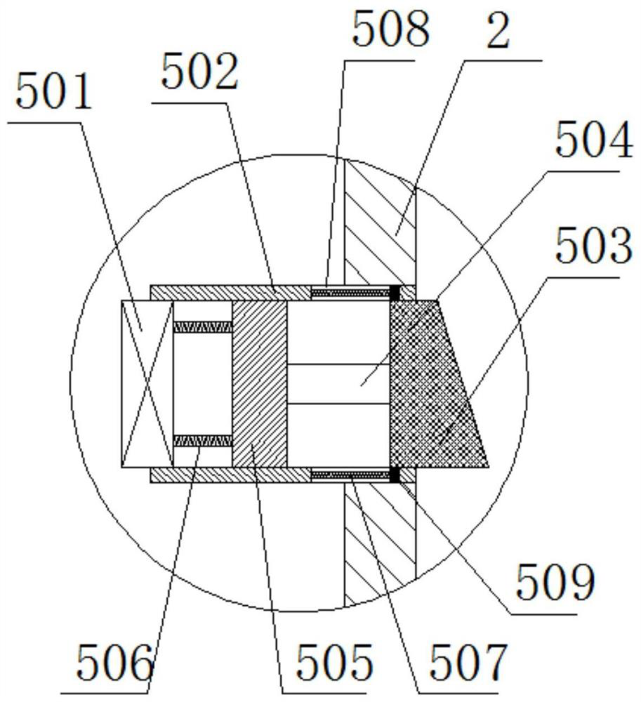
[0062] On the basis of Embodiment 1, in order to ensure that the well flushing pipe is in the downward process, driving the support head of the ultrasonic vibration assembly can make the ultrasonic vibrator in the ultrasonic vibration assembly 5 closely interfere with the inner wall of the liquid return pipe, and the fixation is stable, such as image 3 The ultrasonic vibration assembly 5 includes parallel base pipes 502 fixedly connected to both sides of the inner sleeve 2 and communicated with the inner sleeve 2, one end of the parallel base pipes 502 is provided with an ultrasonic vibrator 501, and the ultrasonic vibrator 501 is connected to the device. The slider 505 in the parallel base pipe 502 is fixedly connected by a compression spring 506, and the slider 505 is connected with the super wave vibrator by a compression spring 506 to ensure that the ultrasonic vibrator is pushed to contact with the inner wall of the liquid return pipe with a certain The cushioning and adj...

Embodiment 3

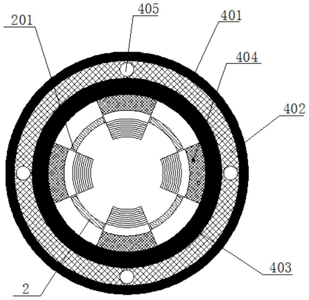
[0066] On the basis of Example 1 or Example 2, it is ensured that when the well flushing pipe goes down, the annular space between the liquid return pipe and the inner casing can be fully sealed and sealed, and at the same time, it is ensured that when the device is not lowered, no It will affect the efficiency of the liquid return pipe, such as figure 2The packing assembly 4 includes an outer sealing rubber ring body 401 in sealing contact with the inside of the liquid return pipe 1, a base ring body 402 set in the outer sealing rubber ring body 401, and a rubber expansion ring body set in the base ring body 402. The ring body 403 is fixedly connected to a plurality of trapezoidal tiles 404 in the rubber expansion ring body 403; the end of the slope of each trapezoidal tile 404 extends to the inner casing 2 through the through hole 201 provided on the inner casing 2 During operation, the outer sealing rubber ring body 401 can be in sealing contact with the inner wall of the ...


PUM


Abstract

The invention relates to an ultrasonic vibration combined type well washing device and a well washing method. The ultrasonic vibration combined type well washing device comprises an inner sleeve arranged in a liquid return pipe in a well and a well washing pipe arranged in the inner sleeve, and the end of the well washing pipe extends out of the liquid return pipe. A blocking assembly sleeves theupper portion of the inner sleeve. A plurality of liquid return through holes are formed in the blocking assembly, and a one-way regulating valve is arranged in each liquid return through hole. An ultrasonic vibration assembly is arranged on the lower portion of the inner sleeve, and a cleaning fluid injection assembly is arranged at the bottom of the inner sleeve. A blocking assembly opening headand an ultrasonic vibration assembly supporting head are arranged outside the well washing pipe from top to bottom, and a cleaning fluid injection assembly opening plug communicated with the well washing pipe is arranged at the bottom of the well washing pipe. The sealing performance is improved, the efficiency of the well washing operation is improved, and the time of the well washing operationis saved.

Description

technical field [0001] The invention relates to the technical field of water supply source wells, hydrogeological drilling and geothermal well flushing, in particular to an ultrasonic vibration composite well flushing device and a well flushing method. Background technique [0002] The cuttings produced during the construction of water source wells, hydrogeological drilling and geothermal wells, as well as the original debris in the cracks of the surrounding rock of the drilling will affect the migration of groundwater to varying degrees, and even cause small-scale cracks to be blocked. Seriously reduce pumping efficiency or post-water supply effect; [0003] At the same time, during the production process of water supply wells, geothermal wells and water source wells, after a certain period of extraction and recharge, because the groundwater usually contains minerals, organic substances and special components, etc., it is easy to corrode the pipes in the wells, and the temp...

Claims


Application Information

Patent Timeline
Patent Type & Authority Applications(China)
IPC IPC(8): E21B37/00E21B28/00E21B34/08E21B33/129
CPCE21B37/00E21B28/00E21B34/08E21B33/129Y02E10/10
Inventor 严其孙家应严家平
Owner NO 1 SURVEYING TEAM OF ANHUI CHARCOAL FIELD & GEOLOGY BUREAU
Learn More