
Desulfurization wastewater recycling process based on composite membrane system

A technology for desulfurization wastewater and treatment process, applied in membrane technology, semi-permeable membrane separation, water/sewage treatment, etc., can solve the problems of increased operating cost and reduced total wastewater recovery rate of wastewater zero-discharge system, and achieve excellent operation stability. , the effect of reducing the floor space and operating costs, and inhibiting the tendency of scaling

Active Publication Date: 2020-03-31
HUANENG SHANDONG POWER GENERATION CO LTD +1
View PDF6 Cites 0 Cited by
  • Summary
  • Abstract
  • Description
  • Claims
  • Application Information

AI Technical Summary

Problems solved by technology

[0005] Although the arrangement of the membrane system increases, the ability to treat complex wastewater will be stronger, but after combining too many membrane treatment units, the total wastewater recovery rate of the composite membrane system will decrease, and the amount of wastewater that needs to be evaporated will increase. , leading to a sharp increase in the operating costs of the entire wastewater zero discharge system

Method used


Image

  • Desulfurization wastewater recycling process based on composite membrane system
  • Desulfurization wastewater recycling process based on composite membrane system
  • Desulfurization wastewater recycling process based on composite membrane system

Examples


Embodiment approach

[0055] 本发明的第三种实施方式,提供了一种上述改性陶瓷膜在脱硫废水处理中的应用。

[0056] 本发明的第四种实施方式,提供了一种复合膜系统,包括依次连接的陶瓷膜过滤单元和反渗透膜过滤单元,所述陶瓷膜过滤单元采用的陶瓷膜为上述改性陶瓷膜。

[0057] 该实施方式的一种或多种实施例中,包括第一过滤器,第一过滤器的出口连接陶瓷膜过滤单元的进口。

[0058] 该系列实施例中,所述第一过滤器为叠片式过滤器。

[0059] 该系列实施例中,第一过滤器与陶瓷膜过滤单元之间设有增压泵,增压泵的出口连接陶瓷膜过滤单元的进口。

[0060] 该实施方式的一种或多种实施例中,包括第二过滤器,第二过滤器的进口与陶瓷膜过滤单元处理水出口连接,第二过滤器的出口与反渗透膜过滤单元的进口连接。

[0061] 该系列实施例中,所述第二过滤器为保安过滤器。

[0062] 该系列实施例中,第二过滤器与反渗透膜过滤单元之间设有高压泵,高压泵的出口与反渗透膜过滤单元的进口连接。

[0063] 该实施方式的一种或多种实施例中,包括清洗泵,所述清洗泵进口与反渗透膜过滤单元的出口连接。

[0064] 本发明的第五种实施方式,提供了一种基于复合膜系统的脱硫废水回收再利用工艺,采用上述复合膜系统,脱硫废水先经过改性陶瓷膜过滤处理,然后进行反渗透处理。

[0065] 改性陶瓷膜和反渗透膜均采用错流式过滤方式。

[0066] 该实施方式的一种或多种实施例中,改性陶瓷膜过滤处理的脱硫废水处理量为310~330L / (h·m 2 ),初始进水压力为0.19~0.21MPa,水回收率控制在97%以上。

[0067] 该实施方式的一种或多种实施例中,反渗透处理中,初始进水压力为1.0~2.5MPa,水回收率控制在85%以上。

[0068] 该实施方式的一种或多种实施例中,改性陶瓷膜的除盐水在0.2MPa下的通量为800L / (h·m 2 ),反渗透系统在1.0MPa下水回收率不低于90%(电导率2000ppm)。陶瓷膜过滤单元为一级一段工艺,反渗透膜过滤单元为一级两段工艺。

[0069] 该实施方式的一种或多种实施例中,陶瓷膜过滤单元的浓水和反渗透膜过滤单元的浓水导入下级蒸发单元进行进一步浓缩。

[0070] 该实施方...

Embodiment 1

[0078] 将截留孔径为50nm的陶瓷膜先用3%的盐酸浸泡12h,而后外加超声,继续清洗1h。然后用除盐水清洗至清洗液pH不低于5.5。然后将处理后的陶瓷膜浸泡在1%的Fe(NO 3 ) 3 、0.1%的Mn(NO 3 ) 2 和0.1%的Co(NO 3 ) 2 混合溶液中,静置吸附24h后,用除盐水清洗至无色,烘干后放入马弗炉中进行煅烧。煅烧过程为先以4℃ / min升温至500℃,保温4h,再以2℃ / min升温至800℃,保温2h,冷却后用1%的盐酸清洗至无色,再用除盐水清洗至pH不低于5.5,获得改性陶瓷膜。

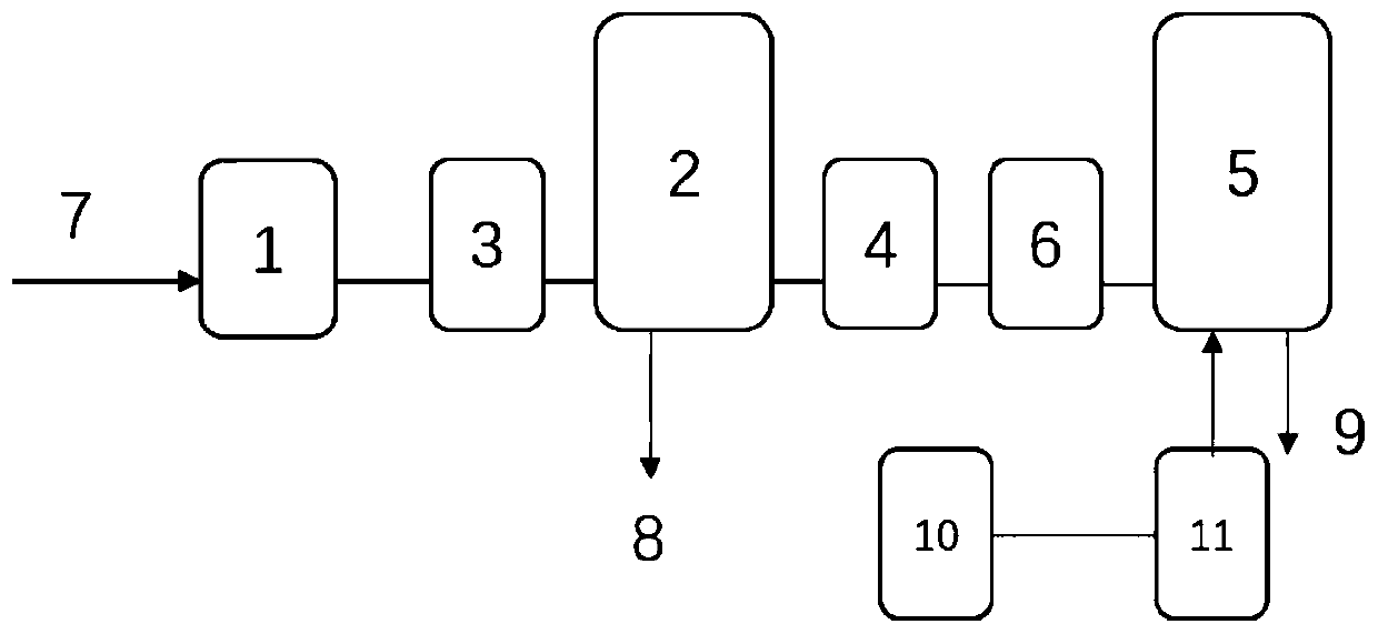
[0079] 一种复合膜系统,如 figure 1 所示,包括依次连接的叠片式过滤器1、增压泵3、陶瓷膜单元2、保安过滤器4、高压泵6、反渗透单元5,脱硫废水入口7为叠片式过滤器1的 import. 陶瓷膜单元2的浓水出口、反渗透单元5的浓水出口连接下级蒸发单元。 清洗泵11的进口连接清洗罐10,清洗泵11的出口连接反渗透单元5。

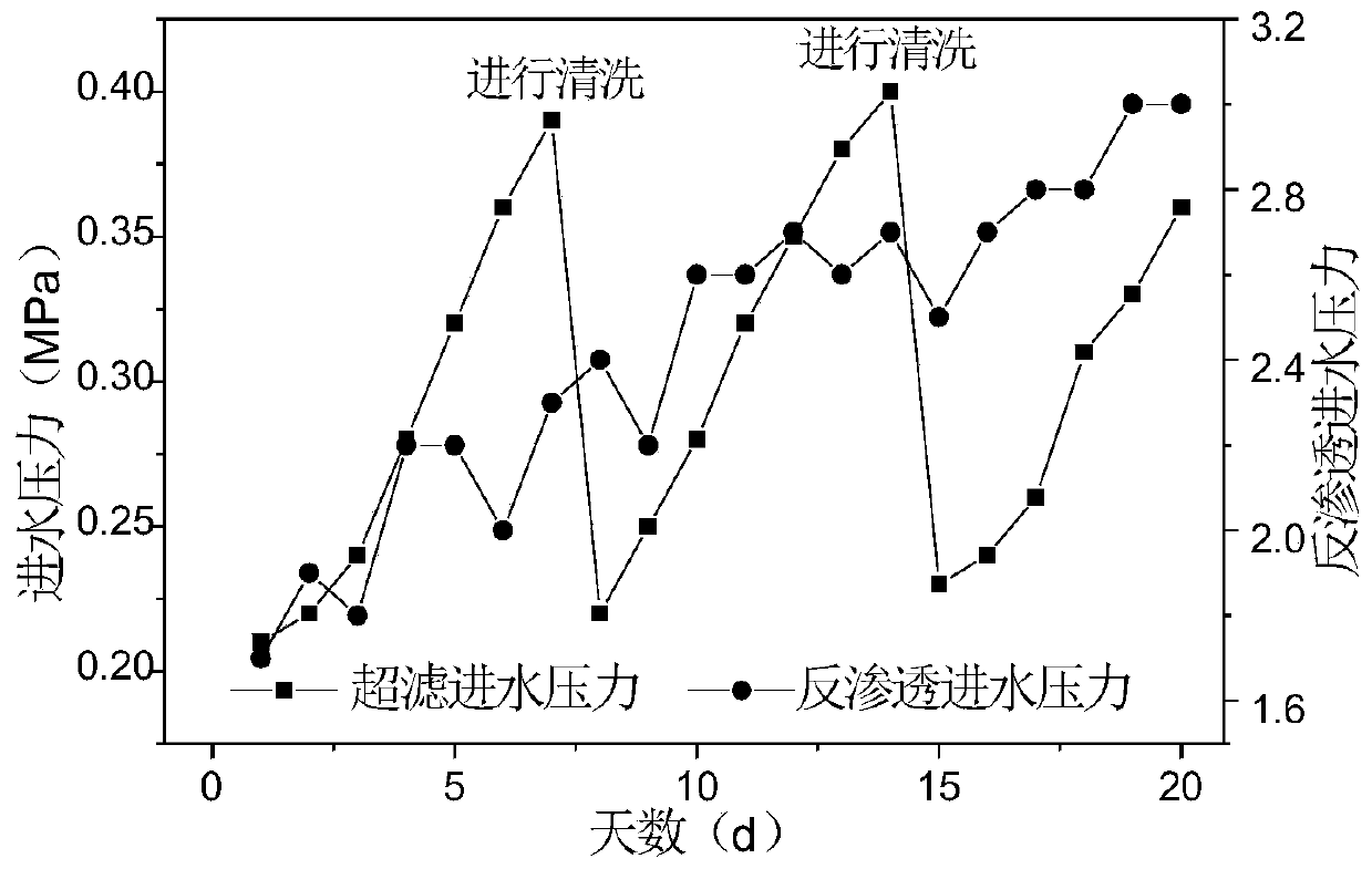
[0080] 其工艺为:将脱硫废水导入复合膜系统,陶瓷膜处理单元脱硫废水处理量为320L / (h·m 2 ),进水压力为0.2MPa,水回收率控制在97%以上。陶瓷膜出水而后导入反渗透处理单元中,进水压力为1.0-2.5MPa,水回收率控制在85%以上。

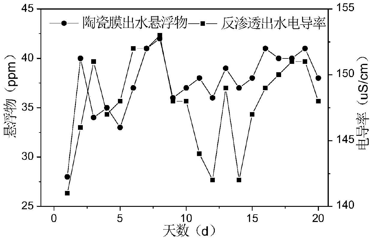
[0081] 水质测定为:悬浮物的测定采用重量法,即取一定体积的废水采用抽滤的方式通过0.45um的超滤膜,再测量废水通过前后超滤膜质量的变化,进行悬浮物含量的测定。含盐量的测定采用电导率测试仪表的含盐量测试功能,电导率仪为美国Thermal公司生产的CON700电导率仪。


PUM

PropertyMeasurementUnit
recovery rateaaaaaaaaaa

Abstract

The invention discloses a desulfurization wastewater recycling process based on a composite membrane system. The treatment process of a ceramic membrane adopted in the composite membrane system comprises the following steps: soaking the ceramic membrane in diluted hydrochloric acid; then placing the soaked ceramic membrane in a salt solution containing ferric nitrate, manganese nitrate and cobaltnitrate for adsorption treatment, calcining the ceramic membrane subjected to adsorption treatment in an air atmosphere, and cleaning the calcined ceramic membrane with diluted hydrochloric acid and water in sequence; wherein the diluted hydrochloric acid is an HCl solution with the mass fraction not higher than 5%. According to the process, the desulfurization wastewater is treated, the concentration efficiency of the desulfurization wastewater is improved, a recyclable water source is obtained, the evaporation capacity of final concentrated water is reduced, and meanwhile, the stable operation of the whole membrane system is ensured.

Description

technical field [0001] The invention belongs to the field of waste water treatment and recycling, and relates to a combination technology based on a special treatment ceramic membrane and a reverse osmosis membrane, in particular to a technology for recycling desulfurization wastewater based on a composite membrane system. Background technique [0002] The information disclosed in this background section is only intended to increase the understanding of the general background of the present invention, and is not necessarily taken as an acknowledgment or any form of suggestion that the information constitutes the prior art already known to those skilled in the art. [0003] With the increasing demand for power generation and heat supply, the amount of desulfurization wastewater produced by various power plants is increasing. Since desulfurization wastewater belongs to the terminal wastewater of the whole plant, it has the characteristics of many types of pollutants, complex wa...

Claims


Application Information

Patent Timeline
Patent Type & Authority Applications(China)
IPC IPC(8): B01D67/00B01D69/12B01D65/06C02F9/02
CPCB01D67/0093B01D65/02C02F1/001C02F1/44C02F1/441B01D69/12C02F2303/14Y02A20/131
Inventor 焦绪常高冰孙业富李亚明李尊峰王蕴宏张志霞杜纪明
Owner HUANENG SHANDONG POWER GENERATION CO LTD
Learn More