Water pump cooling device for thermal power plant

A technology for cooling devices and thermal power plants, applied to pump devices, parts of pumping devices for elastic fluids, pumps, etc., can solve problems such as damage to parts

Pending Publication Date: 2021-02-23
兖矿能源集团股份有限公司
View PDF0 Cites 2 Cited by
  • Summary
  • Abstract
  • Description
  • Claims
  • Application Information

AI Technical Summary

Problems solved by technology

[0005] An embodiment of the present invention provides a cooling device for a water pump in a thermal power plant to solve the technical problem of dama

Method used


Image

  • Water pump cooling device for thermal power plant
  • Water pump cooling device for thermal power plant
  • Water pump cooling device for thermal power plant

Examples


Embodiment Construction

[0024] In order to enable those skilled in the art to better understand the technical solutions in the present application, the technical solutions in the embodiments of the present application will be clearly and completely described below in conjunction with the drawings in the embodiments of the present application. Apparently, the described embodiments are only some of the embodiments of this application, not all of them. Based on the embodiments in this application, all other embodiments obtained by persons of ordinary skill in the art without creative efforts shall fall within the scope of protection of this application.

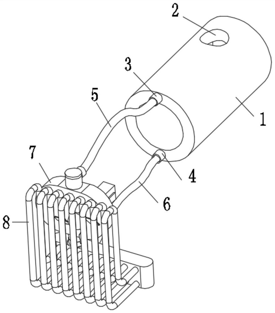
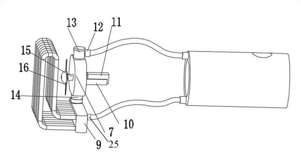
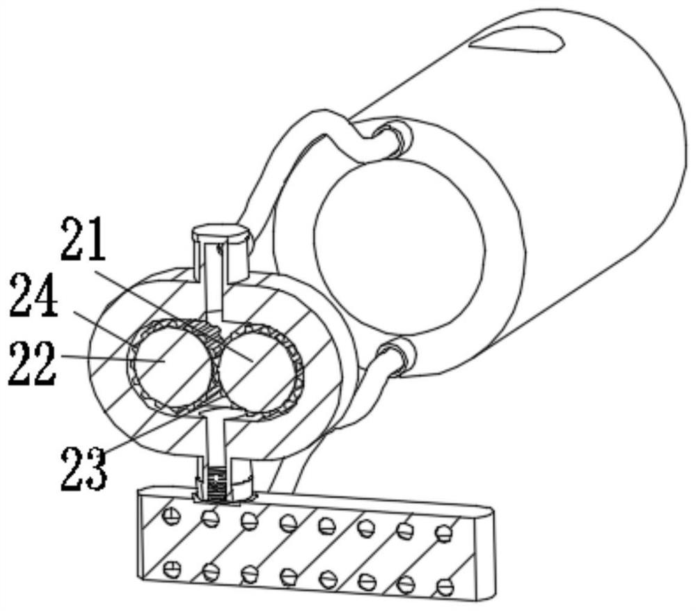
[0025] figure 1 It is a schematic structural diagram of a water pump cooling device for a thermal power plant provided by an embodiment of the present invention from the main perspective, figure 2 It is a structural schematic diagram of a water pump cooling device for a thermal power plant provided by an embodiment of the present invention, viewed fr...


PUM


Abstract

The invention provides a water pump cooling device for a thermal power plant. According to the water pump cooling device for the thermal power plant, cooling water is injected into the pump sleeve, acooling water circulation system is formed by the pump sleeve, a water outlet pipe, a water inlet pipe, a driving box, a heat dissipation box and a heat dissipation water pipe, a driving motor drivesa driving wheel to rotate, and then the meshing effect of first teeth and second teeth is utilized, so that the cooling water sequentially passes through the water outlet pipe, the driving box, the heat dissipation box, the heat dissipation water pipe and the water inlet pipe from the pump sleeve and flows back into the pump sleeve, and cooling water circulation is completed; and in addition, thedriving motor drives a heat dissipation fan to rotate to achieve air cooling and heat dissipation of the water pump. The device can cool the water pump for the thermal power plant, and has the characteristics of long-distance heat dissipation, small cooling water flow, convenience in keeping the temperature of the water pump, easiness in disassembly and assembly and easiness in transportation.

Description

technical field [0001] The invention belongs to the technical field of industrial equipment, in particular to a water pump cooling device for thermal power plants. Background technique [0002] There are two types of heating methods: distributed heating and centralized heating. Distributed heating at the user's site, due to the limitation of the heating scale, only small boilers with low parameters and low thermal efficiency can be used (the thermal efficiency is about 50%). However, heating by thermal power plants forms district heating. Due to the large heating scale, large boilers with high parameters and high efficiency can be used (the thermal efficiency is above 85%), thereby greatly improving energy utilization efficiency and saving fuel. [0003] Thermal power plants need to use water pumps for heat source circulation. The heat source is mainly hot water. Therefore, the entire water pump works at high temperature for a long time without cooling equipment. Excessive...

Claims


Application Information

Patent Timeline
IPC IPC(8): F04B53/08F04B53/22F04C11/00F04C2/18F04D25/08
CPCF04B53/08F04B53/22F04C2/18F04C11/00F04D25/08
Inventor 马彦任海燕辛爽惠保安侯洪杰梁路刘娟徐志刚黄勇
Owner 兖矿能源集团股份有限公司
Why Eureka
Try Eureka