Gravity type venturi air volume control valve
An air volume control and Venturi technology, applied in the field of gravity venturi air volume control valve, can solve the problems of slow surface wind speed control, difficult and frequent pressure differential accurate detection, etc., to save components, reduce costs, and simplify the structure.
- Summary
- Abstract
- Description
- Claims
- Application Information
AI Technical Summary
Problems solved by technology
Method used
Image

Examples
Embodiment 1
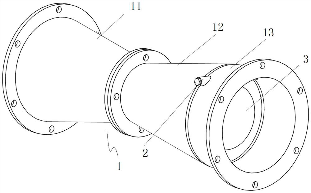
[0031] Such as figure 1 As shown, a gravity-type Venturi air volume control valve includes a valve body 1 , the valve body 1 includes a shrinking pipe section 11 , a flared pipe section 12 and a horizontal pipe section 13 , and the rotating shaft 2 is arranged on the horizontal pipe section 13 . The ratio of the maximum pipe diameter to the minimum pipe diameter of the shrinkage pipe section 11 is 2:1. The ratio of the maximum pipe diameter to the minimum pipe diameter of the flared pipe section 12 is 2:1. The horizontal pipe section 13 is arranged at the flared opening of the flared pipe section 12 , and its inner diameter is equal to the maximum inner diameter of the flared pipe section 12 .
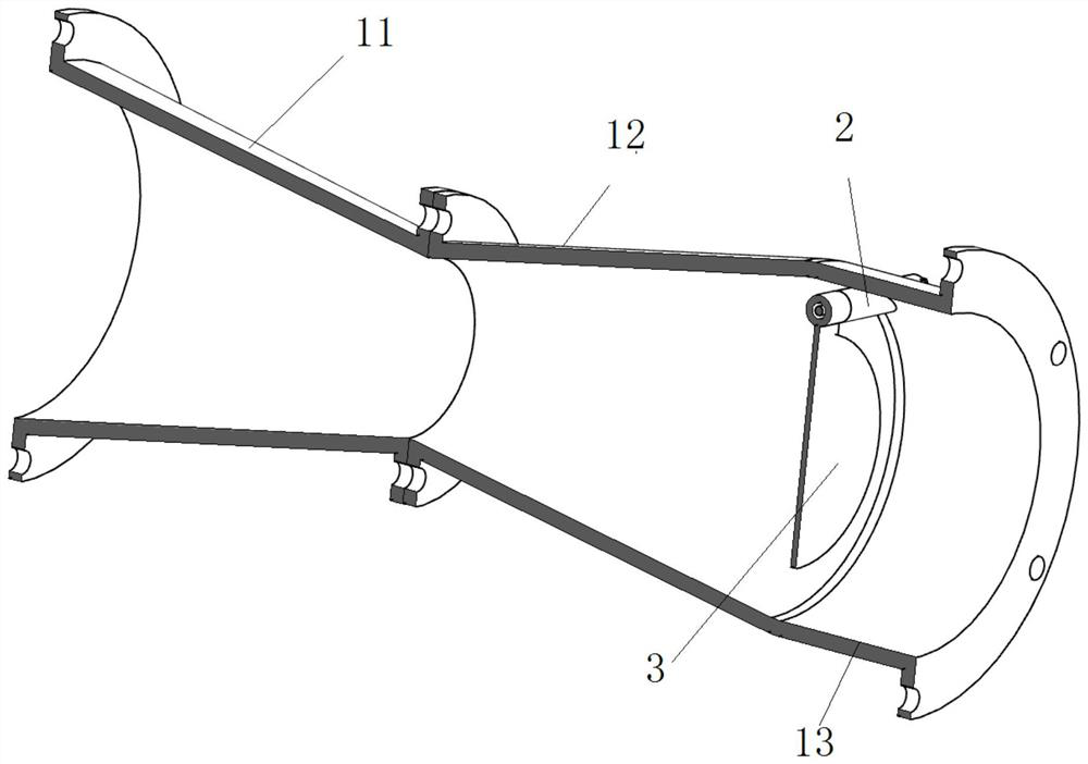
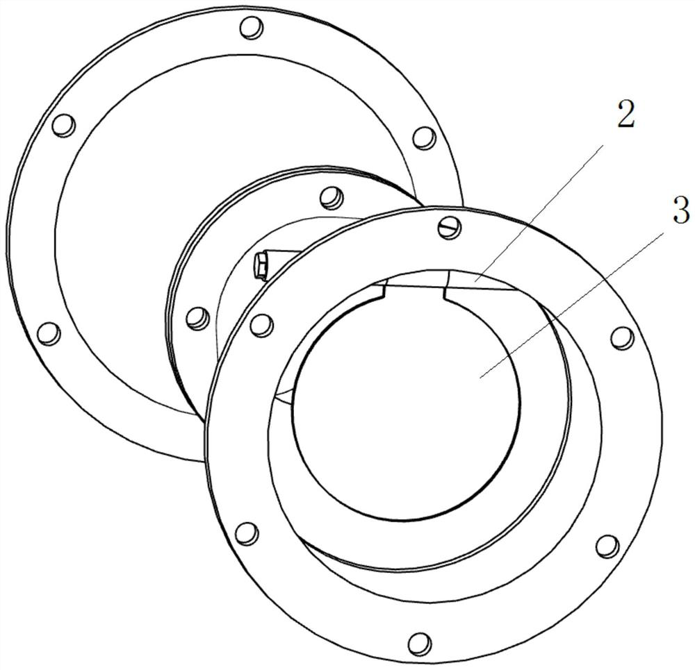
[0032] Such as Figure 2-3 As shown, the valve body 1 is provided with a rotating shaft 2, and the rotating shaft 2 is arranged laterally on one side inner wall of the horizontal pipe section 13, and the distance between the top of the rotating shaft 2 and the inner wall of the horiz...
Embodiment 2
[0036] The ratio of the maximum pipe diameter to the minimum pipe diameter of the shrinkage pipe section 11 is 1.5:1. The ratio of the maximum pipe diameter to the minimum pipe diameter of the flared pipe section 12 is 1.5:1.
[0037] The distance between the top of the rotating shaft 2 and the inner wall of the horizontal pipe section 13 is 3mm.
[0038] The relationship between the area S1 of the valve plate 3 and the lateral area S2 of the valve body 1 where the valve plate 3 is located is: S1=0.5S2.
[0039] The material of the rotating shaft 2 is PTFE, and the compressive strength range is about 25MPa
[0040] The material of the valve plate 3 is LDPE, and the thickness is 10MM.
[0041] All the other are with embodiment 1.
Embodiment 3
[0043] The ratio of the maximum pipe diameter to the minimum pipe diameter of the shrinkage pipe section 11 is 3:1. The ratio of the maximum pipe diameter to the minimum pipe diameter of the flared pipe section 12 is 3:1.
[0044] The distance between the top of the rotating shaft 2 and the inner wall of the horizontal pipe section 13 is 10 mm.
[0045] The relationship between the area S1 of the valve plate 3 and the lateral area S2 of the valve body 1 where the valve plate 3 is located is: S1=0.95S2.
[0046] The material of the rotating shaft 2 is PTFE, and the compressive strength range is about 25MPa
[0047] The material of the valve plate 3 is LDPE, and the thickness is 10MM.
[0048] All the other are with embodiment 1.
[0049] when using it,
[0050] The gravity type Venturi air volume control valve of each of the above-mentioned embodiments is installed in the air duct, and the end of the necking pipe section 11 is connected to the exhaust fan, and the power of ...
PUM
 Abstract
Description
Claims
Application Information
 - R&D
- Intellectual Property
- Life Sciences
- Materials
- Tech Scout
- Unparalleled Data Quality
- Higher Quality Content
- 60% Fewer Hallucinations
Browse by: Latest US Patents, China's latest patents, Technical Efficacy Thesaurus, Application Domain, Technology Topic, Popular Technical Reports.
© 2025 PatSnap. All rights reserved.Legal|Privacy policy|Modern Slavery Act Transparency Statement|Sitemap|About US| Contact US: help@patsnap.com