
Micro blood flow image segmentation quantification method and system based on multi-dimensional feature space

An image segmentation and multi-dimensional feature technology, applied in the field of biomedical imaging, can solve the problems of lack of theoretical support, complex calculation, low motion contrast, etc., to achieve the effect of improving visibility

Pending Publication Date: 2021-02-23
ZHEJIANG UNIV
View PDF0 Cites 0 Cited by
  • Summary
  • Abstract
  • Description
  • Claims
  • Application Information

AI Technical Summary

Problems solved by technology

However, simple intensity masks lead to high classification error rates and low motion contrast due to complex dependencies between decorrelation coefficients and signal intensity
[0005] Most of the existing OCTA classification methods lack strong theoretical support, and are interfered by the difference between the template parameters and the actual biological tissue, and cannot clearly distinguish the accurate classification of dynamic and static signals; or use complex estimators to modify the signal-to-noise ratio to decorrelate The influence of the calculation is complex and the background noise caused by the static area cannot be removed

Method used


Image

  • Micro blood flow image segmentation quantification method and system based on multi-dimensional feature space
  • Micro blood flow image segmentation quantification method and system based on multi-dimensional feature space
  • Micro blood flow image segmentation quantification method and system based on multi-dimensional feature space

Examples


Embodiment Construction

[0057] Specific embodiments of the present invention will be described in detail below in conjunction with the accompanying drawings, which form a part of the present invention. It should be noted that these descriptions and examples are illustrative only, and should not be construed as limiting the scope of the present invention. The protection scope of the present invention is defined by the appended claims, and any changes based on the claims of the present invention are It is the protection scope of the present invention.

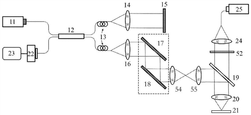
[0058] figure 2 Shown is a schematic structural diagram of an acquisition device of the ID space-based OCT angiography technique in the present invention. The main structure of the low-coherence interferometric part of the device is an interferometer, which is composed of 11-23. The light emitted by the light source 11 is divided into two beams by the beam splitter 12: one beam of light enters the reference arm of the interferometer through a polariz...


PUM


Abstract

The invention discloses a micro blood flow image segmentation quantification method and system based on a multi-dimensional feature space. A scattering signal acquisition method comprises the following steps of: acquiring a three-dimensional space scattering signal of a biological tissue sample, extracting a signal-to-noise ratio reciprocal and a decorrelation coefficient, and constructing a microblood flow image. A blood flow image segmentation method comprises the steps: constructing a signal-to-noise ratio reciprocal-decorrelation coefficient two-dimensional feature space, setting a segmentation threshold line, and carrying out the reservation to obtain a binary micro blood flow image; the invention discloses a blood flow form quantification method, which comprises the following stepsof: extracting a blood flow skeleton and a blood flow contour according to a binarized micro blood flow image, and further calculating various quantification parameters reflecting a blood flow form. According to the method, the blood flow signal in the blood flow image can be adaptively segmented according to the signal-to-noise ratio, the blood flow of more deep tissues is reserved, and the segmentation quantification result reflecting the blood flow form is obtained according to the blood flow segmentation result.

Description

technical field [0001] The present invention generally relates to the field of biomedical imaging, and more specifically relates to optical coherence tomography (Optical Coherence Tomography, OCT) and optical coherence tomography (OCT Angiography, OCTA) associated blood flow imaging methods and Segmentation method of micro-flow images based on multi-dimensional feature space. Background technique [0002] Blood flow is an important indicator to measure physiological function and pathological state. Currently, the commonly used blood flow angiography technique requires intravenous injection of exogenous markers, and the possible side effects make it unsuitable for long-term and frequent monitoring of human blood flow. Track detection and the physical condition of some patients. In recent years, OCTA, a blood flow imaging technique developed on the basis of optical coherence tomography, replaces traditional exogenous fluorescent markers with endogenous blood flow movement. T...

Claims


Application Information

Patent Timeline
IPC IPC(8): G06T7/136G06T7/12G06K9/00A61B5/026
CPCG06T7/136G06T7/12A61B5/0261A61B5/0033G06T2207/10101G06T2207/30104G06F2218/04G06F2218/12
Inventor 李鹏张一铭李花坤
Owner ZHEJIANG UNIV
Learn More