
High-efficiency drilling device for stone engraving

A drilling device and high technology, applied in the field of drilling devices for stone carving, can solve the problems of inability to guarantee drilling efficiency and inability to control the temperature at the drilling site in real time, so as to improve the effect and reliability, and improve the drilling efficiency. , the effect of saving consumption

Inactive Publication Date: 2021-02-26
耒阳市盛唐石业有限公司
View PDF1 Cites 0 Cited by
  • Summary
  • Abstract
  • Description
  • Claims
  • Application Information

AI Technical Summary

Problems solved by technology

The stone drilling device in the above-mentioned patent has the following disadvantages: although it can meet certain drilling requirements, it cannot control the temperature at the drilling site in real time according to the rotation speed, so the drilling efficiency cannot be guaranteed.

Method used


Image

  • High-efficiency drilling device for stone engraving
  • High-efficiency drilling device for stone engraving
  • High-efficiency drilling device for stone engraving

Examples


Embodiment 1

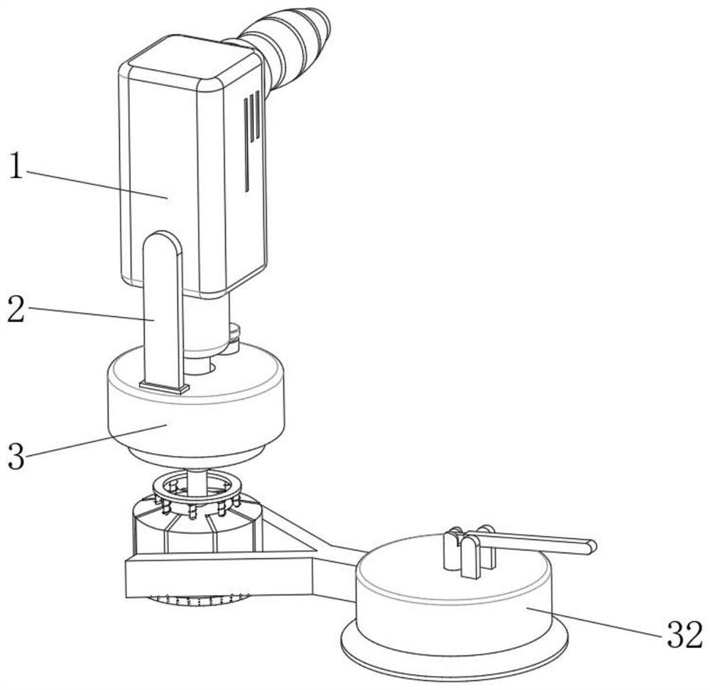
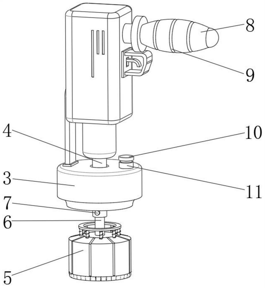
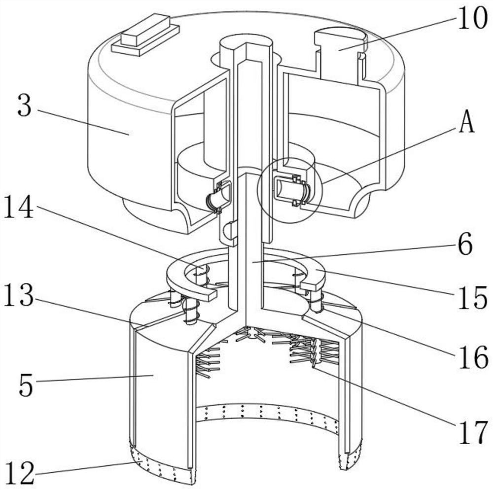
[0033] A more efficient drilling device for stone carving, such as Figure 1-6 As shown, it includes a drill main body 1 and a positioning mechanism 32. An output shaft 4 is provided on one side of the drill main body 1. The output shaft 4 is connected to a connecting shaft 6 through a fixed pin 7. The connecting shaft 6 passes through the fixed pin 7 and the output shaft. 4 After transmission, driven by the motor in the main body 1 of the drill, the outer wall of the bottom of the connecting shaft 6 is welded with an annular tool seat 5, and the outer wall of the bottom of the annular tool seat 5 is integrally provided with an annular drill 12. The main body of the drill gun 1 is The side outer wall is equipped with a water storage box 3 through the connecting frame 2, the water storage box 3 is located outside the output shaft 4, and the inner wall of the circumference of the water storage box 3 close to the output shaft 4 is integrally provided with a linkage rubber head 19,...

Embodiment 2

[0041] A more efficient drilling device for stone carving, such as figure 1 , Figure 5 As shown, in order to facilitate positioning; this embodiment makes the following improvements on the basis of Embodiment 1: the positioning mechanism 32 includes a positioning bracket 29 and a fixing seat 21, and the positioning bracket 29 is fixed to the outer wall of the side of the fixing seat 21 by screws. The shape of the bracket 29 is adapted to the annular knife seat 5, and the bottom of the fixed seat 21 is bonded with a suction cup 28; by setting the positioning bracket 29, the fixed seat 21 and other structures, the annular knife seat 5 can be limited, thereby improving the accuracy of drilling. Spend.

[0042] In order to further improve the positioning effect; such as Figure 5 As shown, the inner wall of the bottom of the fixed seat 21 is sealed and movable connected with a lifting plug 27, and the outer wall of the top of the lifting plug 27 is fixed with a lifting rod 22 b...


PUM


Abstract

The invention discloses a high-efficiency drilling device for stone engraving, relates to the technical field of stone engraving and drilling devices, and aims to conveniently control the cooling liquid adding amount based on the rotating speed. A drilling gun body and a positioning mechanism are specifically included, an output shaft is arranged on one side of the drilling gun body and connectedwith a connecting shaft through a fixing pin, an annular tool apron is welded to the outer wall of the bottom of the connecting shaft, an annular drilling tool is integrally arranged on the outer wallof the bottom of the annular tool apron, and a water storage box is installed on the outer wall of one side of the drilling gun body through a connecting frame. The water storage box is located on the outer side of the output shaft, a linkage rubber head is integrally arranged on the circumferential inner wall, close to the output shaft, of the water storage box and is of a hollow structure, anda water leakage groove is formed in the outer wall of one side of the linkage rubber head. By means of the high-efficiency drilling device for stone engraving, cooling liquid flows out along with rotation of the output shaft, the purpose that the output quantity of the cooling liquid is in direct proportion to the rotating speed of the output shaft is achieved, the drilling efficiency is improved,and meanwhile the consumption of the cooling liquid is reduced.

Description

technical field [0001] The invention relates to the technical field of stone carving and drilling devices, in particular to a high-efficiency drilling device for stone carving. Background technique [0002] In the stone carving process, drilling operations are often required. At this time, various drilling tools are usually used for drilling. However, during the drilling process, the drilling mechanism is constantly rubbing against the stone surface. In order to improve the drilling efficiency, And the service life of the protection device often needs to apply coolant to the drill hole. Although the current stone carving drilling device can meet certain drilling requirements, it lacks controllability in adding coolant and cannot Changing the amount of coolant added in real time according to the rotational speed may cause too little coolant to reduce efficiency, or too much coolant to cause pollution and waste, and the effect of reasonable temperature control cannot be achiev...

Claims


Application Information

Patent Timeline
Patent Type & Authority Applications(China)
IPC IPC(8): B28D1/14B28D1/30B28D7/00B28D7/02B28D7/04
CPCB28D1/14B28D1/30B28D7/00B28D7/02B28D7/046
Inventor 李晓雪罗美林刘洪光李珍珍
Owner 耒阳市盛唐石业有限公司
Learn More