a shock absorber
A shock absorber and solenoid valve technology, applied in the field of vehicles, can solve the problems of difficulty in meeting the requirements of vehicle driving stability and poor vibration damping performance, and achieve the effects of improving the riding experience, improving the stability, and improving the stability.
- Summary
- Abstract
- Description
- Claims
- Application Information
AI Technical Summary
Problems solved by technology
Method used
Image
Examples
Embodiment
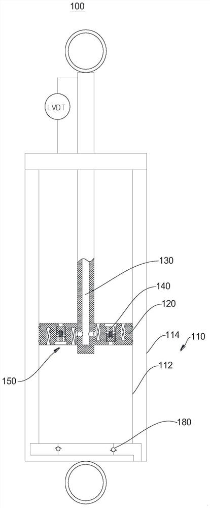
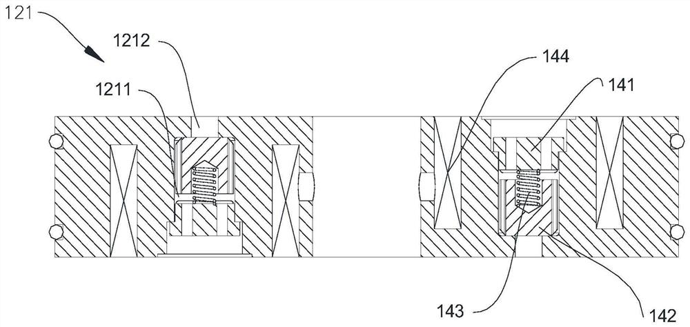
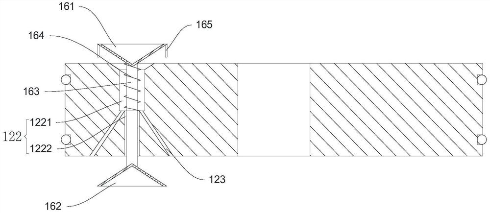
[0067] Please refer to figure 1 , the present embodiment provides a shock absorber 100, which is used to be installed between the vehicle frame and the suspension, so as to reduce the vibration between the vehicle body and the wheels. The above-mentioned shock absorber 100 includes an outer cylinder 110, a piston 120, a rod of the piston 120 and two electromagnetic valves; the outer cylinder 110 is connected with the suspension, the piston 120 is slidably arranged in the outer cylinder 110, and one end of the piston 120 sticks out of the outer cylinder 110 to connect with the vehicle. frame connection. The upper chamber and the lower chamber of the piston 120 are filled with hydraulic oil, and two solenoid valves are arranged on the piston 120. By adjusting the opening of the solenoid valve, the flow area on the piston 120 can be adjusted, and then the damping force of the shock absorber 100 can be adjusted. .
[0068] Specifically, the outer cylinder 110 includes a coaxial ...
Embodiment 2
[0084] Please refer to Figure 4 , this embodiment provides another shock absorber 100, which is basically the same as Embodiment 1, the difference lies in the partial structure of the throttling assembly.
[0085] In the shock absorber 100 in this embodiment, the throttling assembly is replaced by an adjusting screw 170, and the piston 120 is also provided with a first flow channel 124 and a second flow channel 125, the first flow channel 124 runs through the piston 120, the One end of the second flow channel 125 extends to the end surface of the piston 120 , and the other end connects with the first flow channel 124 . When the adjusting screw 170 is screwed in or out, the effective flow area of the second flow channel 125 can be adjusted; hydraulic oil can pass through the piston 120 through the first flow channel 124 and the second flow channel 125 .
[0086] According to the specific vehicle type and the dead weight of the vehicle, the adjusting screw 170 can be screwed...
Embodiment 3
[0088] This embodiment provides a vehicle, which includes a vehicle frame, four damping springs and four suspensions, and adopts the shock absorber 100 in Embodiment 1 or 2. The above-mentioned damping spring can be directly arranged between the suspension and the vehicle frame, or can be integrated into the above-mentioned shock absorber 100 . The piston 120 rod of the shock absorber 100 is hinged to the vehicle frame, and the lower end of the outer cylinder 110 is hinged to the suspension.
[0089] The vehicle above also includes a controller, a speed sensor, an acceleration sensor and four displacement sensors. The above-mentioned controller can directly use the vehicle-mounted ECU, the speed sensor and the acceleration sensor to detect the moving speed and acceleration of the vehicle frame. One end of the displacement sensor is connected to the outer cylinder 110 of the shock absorber 100, and the other end is connected to the piston 120 rod, which is used for displacemen...
PUM
 Abstract
Description
Claims
Application Information
 - R&D
- Intellectual Property
- Life Sciences
- Materials
- Tech Scout
- Unparalleled Data Quality
- Higher Quality Content
- 60% Fewer Hallucinations
Browse by: Latest US Patents, China's latest patents, Technical Efficacy Thesaurus, Application Domain, Technology Topic, Popular Technical Reports.
© 2025 PatSnap. All rights reserved.Legal|Privacy policy|Modern Slavery Act Transparency Statement|Sitemap|About US| Contact US: help@patsnap.com


