Self-unfolding and self-gathering vibrating type vibrating rod for concrete construction

A technology of concrete and vibrating rods, which is applied in infrastructure engineering, friction transmission devices, belts/chains/gears, etc. It can solve the problems of lower construction quality, low vibrating effect, and small vibrating range, and increase the vibration range , take into account the construction quality, and the effect of pounding efficiency

Inactive Publication Date: 2021-02-26
张光强
View PDF0 Cites 4 Cited by
  • Summary
  • Abstract
  • Description
  • Claims
  • Application Information

AI Technical Summary

Problems solved by technology

[0004] When vibrating concrete, it is necessary to choose a vibrating rod with a suitable diameter, because although a thicker vibrating rod has a larger vibrating range, it will form a larger space when it is pulled out, and the space will not be easy to fill. Thereby reduce construction quality, and the space area that thinner vibrating rod forms when extracting is little, can guarantee construction quality, but its vibrating range is also correspondingly smaller, and vibrating effect is low, and vibrating rod in the prior art , its diameter is fixed and cannot be adjusted. Between the vibrating efficiency and the construction quality, only one can be chosen, and it cannot be both, which has strong limitations.

Method used


Image

  • Self-unfolding and self-gathering vibrating type vibrating rod for concrete construction
  • Self-unfolding and self-gathering vibrating type vibrating rod for concrete construction
  • Self-unfolding and self-gathering vibrating type vibrating rod for concrete construction

Examples


Embodiment 1

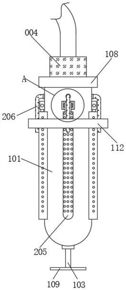
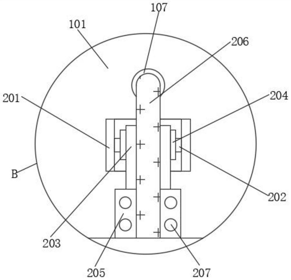
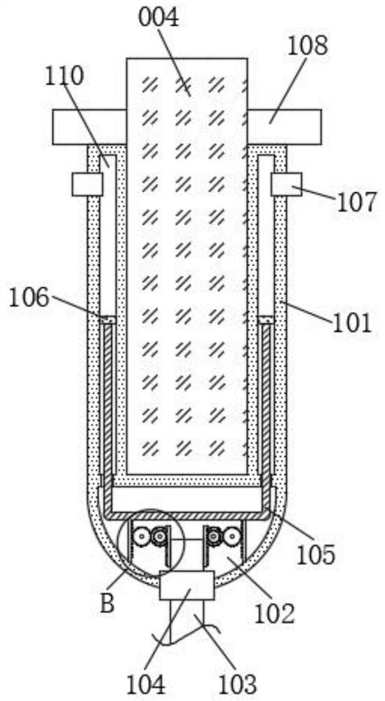
[0042] see figure 1 , image 3 and Figure 5-6 , a self-expanding vibrating vibrator for concrete construction, including a vibrator 004 and a connecting sleeve 101 sleeved on the outer wall of the vibrator 004, and a fastening sleeve is fixed on the outer wall of the vibrator 004. The sealing ring 108, the fastening sealing ring 108 is seamlessly fixedly connected with the top of the connecting sleeve 101, the setting of the fastening sealing ring 108 can improve the stability and sealing of the connection between the vibrator 004 and the connecting sleeve 101, and prevent The connecting sleeve 101 is separated from the vibrator 004, and can prevent the concrete slurry from flowing between the vibrator 004 and the connecting sleeve 101. A transmission groove 102 is opened inside the bottom end of the connecting sleeve 101, and a transmission groove 102 is slidably connected in the transmission groove 102. Drive rod 103, the drive rod 103 slides through the outer wall of the...


PUM


Abstract

The invention discloses a self-unfolding and self-gathering vibrating type vibrating rod for concrete construction, belongs to the technical field of concrete construction, and can realize that underthe linkage of a variable-speed linkage assembly, a driving rod moves up and down relative to a connecting sleeve to drive an annular piston to move up and down, and the annular piston moves upwards to extrude air into a strip-shaped balloon. When the vibrating rod is inserted into concrete, the strip-shaped balloon tends to be horizontally stretched, so that the self-unfolding vibration plate isdriven to be unfolded outwards, when the vibrating rod is inserted into the concrete, the self-unfolding vibration plate can be automatically unfolded, the vibration range of the vibrating rod is effectively enlarged, the vibrating efficiency is improved, and when the vibrating rod is pulled out after vibrating is completed, the self-unfolding vibrating plate can be automatically folded, the spacearea formed when the vibrating rod is drawn out is reduced, then the proper construction amount is guaranteed, the vibrating efficiency and the construction quality can be considered, and on the premise that the construction quality is guaranteed, the vibrating efficiency is effectively improved, and the practicability is remarkably improved.

Description

technical field [0001] The invention relates to the technical field of concrete construction, and more specifically relates to a self-expanding vibrating vibrating rod for concrete construction. Background technique [0002] Vibration refers to the process of vibrating and compacting the concrete mixture unloaded into the pouring bin to improve its strength and ensure the quality of concrete components. When the concrete is poured with a concrete mixer, the air bubbles must be removed and tamped to make the concrete compact and eliminate the honeycomb surface of the concrete, so as to improve its strength and ensure the quality of the concrete components. A concrete vibrator is a machine for mechanically compacting concrete. [0003] When vibrating concrete, it is necessary to achieve "quick insertion and slow extraction". The quick insertion is to prevent the surface concrete from being vibrated first, and the phenomenon of delamination and segregation with the underlying ...

Claims


Application Information

Patent Timeline
Patent Type & Authority Applications(China)
IPC IPC(8): E04G21/08E02D15/02E01C19/38F16H19/04F16J15/16
CPCE01C19/38E02D15/02E02D2300/002E04G21/08F16H19/043F16J15/16
Inventor 张光强
Owner 张光强
Why Eureka
Try Eureka