
Proportional flow valve

A technology of proportional flow valve and spool assembly, which is applied in the direction of lifting valve, valve detail, valve device, etc., can solve the problem of large back pressure, ordinary proportional valve cannot work normally, and it is difficult to meet the requirement that the proportional flow valve is stable at a certain position, etc. problem, to achieve the effect of solving the influence of the proportional flow valve, avoiding air leakage and stabilizing the work

Active Publication Date: 2021-02-26
AMBULANC (SHENZHEN) TECH CO LTD
View PDF7 Cites 6 Cited by
  • Summary
  • Abstract
  • Description
  • Claims
  • Application Information

AI Technical Summary

Problems solved by technology

However, it is difficult to meet the requirement that the proportional flow valve is stable at a certain position during the opening process of the valve port, so the linear relationship between the flow output value and the input signal cannot be realized, and the proportional adjustment of the flow rate cannot be realized.
[0004] In some working conditions, such as a transfer ventilator, the venturi nozzle is usually used to introduce air after the proportional valve, but the gas passing through the proportional valve will generate a large back pressure when passing through the venturi nozzle. It cannot work normally under high pressure conditions, and the proportional adjustment of flow rate cannot be realized.
[0005] So far, there is no proportional flow valve on the market that can solve the above problems

Method used


Image

  • Proportional flow valve
  • Proportional flow valve
  • Proportional flow valve

Examples


Embodiment Construction

[0062] The following will clearly and completely describe the technical solutions in the embodiments of the present invention with reference to the accompanying drawings in the embodiments of the present invention. Obviously, the described embodiments are only part of the embodiments of the present invention, not all of them. Based on the embodiments of the present invention, all other embodiments obtained by persons of ordinary skill in the art without creative efforts fall within the protection scope of the present invention.

[0063] It should be noted that if there is a directional indication (such as up, down, left, right, front, back...) in the embodiment of the present invention, the directional indication is only used to explain the position in a certain posture (as shown in the accompanying drawing). If the specific posture changes, the directional indication will also change accordingly.

[0064] In addition, if there are descriptions involving "first", "second" and ...


PUM


Abstract

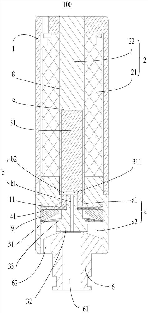
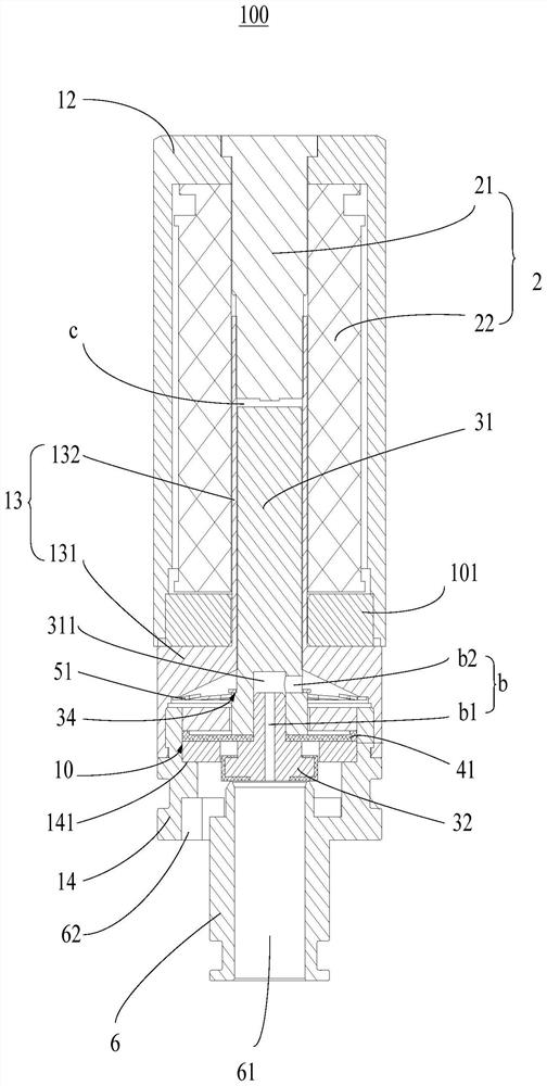
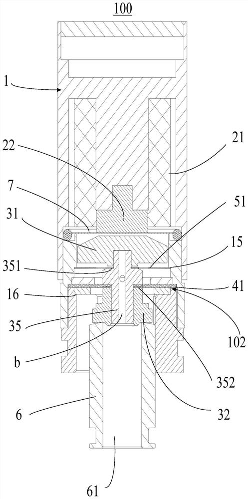
The invention discloses a proportional flow valve. The valve comprises a valve shell assembly, an electromagnet assembly, a valve element assembly, a sealing ring structure and a pre-tightening forcestructure. A mounting cavity is formed in the valve shell assembly, an air inlet base is formed at the open end of the mounting cavity, an air inlet channel extending in the vertical direction is formed in the air inlet base, and the electromagnet assembly is used for providing upward magnetic attraction force. The valve element assembly has an upward moving stroke under driving of magnetic attraction force, an air guide channel is formed in the valve element assembly, an inlet of the air guide channel is formed in the lower end of the valve element assembly and communicates with the air inletchannel, and an outlet of the air guide channel is formed in the side end of the valve element assembly. The sealing ring structure comprises a sealing ring, wherein an inner ring of the sealing ringis sleeved with the valve element assembly, the pre-tightening force structure is arranged between the valve element assembly and the inner wall of the mounting cavity so as to provide downward pre-tightening force for the valve element assembly, and a valve element is stabilized at all working positions through balance between multiple forces. Therefore, the proportional flow valve can stably work on different working conditions, and the influence caused by high back pressure to the proportional flow valve is avoided.

Description

technical field [0001] The invention relates to the technical field of gas flow control and valves, in particular to a proportional flow valve. Background technique [0002] In the proportional flow valve, the flow output value has a linear relationship with the valve core opening, and the valve core opening has a linear relationship with the input electrical signal through an intermediate conversion mechanism, thus determining the linear relationship between the flow output value and the input signal. [0003] Ordinary solenoid valves use an electromagnetic coil and a linear spring structure, and are usually used as an on-off valve, that is, after the electromagnetic coil is energized, it overcomes the spring force to open the valve core, because the electromagnetic force generated by the electromagnetic coil has an exponential relationship with the air gap, while the linear spring and the compression amount Or the stretching amount has a linear relationship. Under the same...

Claims


Application Information

Patent Timeline
IPC IPC(8): F16K1/00F16K1/32F16K1/36F16K1/46F16K27/02F16K27/08F16K31/06
CPCF16K1/00F16K1/32F16K1/36F16K1/46F16K27/029F16K27/08F16K31/0655F16K31/0675A61M16/203A61M16/127F16K39/022F16K2200/3051H01F7/088H01F7/1638H01F7/1607H01F7/121H01F7/081
Inventor 高贵锋饶青超伍倚明邓潇彬王瑞强何杨陈文福于力伟
Owner AMBULANC (SHENZHEN) TECH CO LTD
Learn More