
Fluid system component mechanical property detection device, detection system and detection method

A technology of fluid system and detection device, which is applied in the field of mechanical performance detection of fluid system components, and can solve problems affecting the exposure and positioning process of lithography machines and the exposure quality

Active Publication Date: 2021-02-26
ZHEJIANG CHEER TECH CO LTD
View PDF8 Cites 1 Cited by
  • Summary
  • Abstract
  • Description
  • Claims
  • Application Information

AI Technical Summary

Problems solved by technology

During the flow of the fluid system in the immersion unit, it will generate disturbance force to the projection objective lens, substrate, substrate table carrying the substrate, and the frame of the lithography machine. The diverter block next to the immersion unit is recycled to maintain the immersion unit. During the gas-liquid two-phase separation process of the mixed gas-liquid generated by the fluid flow inside, although the corresponding shock-absorbing or shock-absorbing structure is provided, it will also affect the projection objective lens, the substrate, and the substrate table carrying the substrate. And the whole frame of the lithography machine produces disturbance force; and the above two disturbance forces will change with the flow of the fluid system and the disturbance forces can be superimposed on each other, which will significantly affect the exposure and positioning process of the lithography machine, and ultimately affect Exposure quality, so in the fluid system, especially in the immersion system, the detection of the mechanical properties of components needs fine design and verification detection

Method used


Image

  • Fluid system component mechanical property detection device, detection system and detection method
  • Fluid system component mechanical property detection device, detection system and detection method
  • Fluid system component mechanical property detection device, detection system and detection method

Examples


Embodiment 1

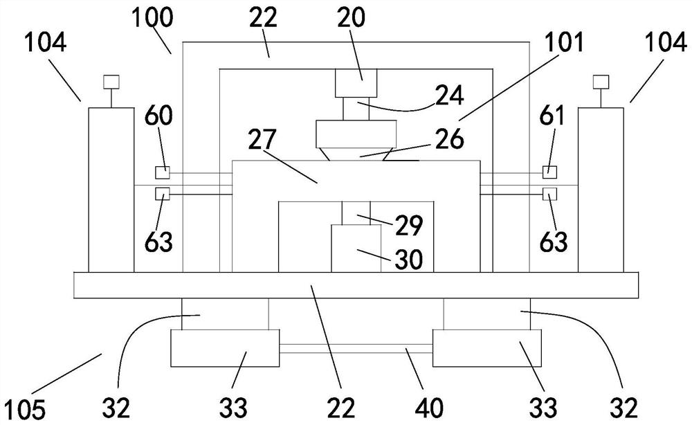
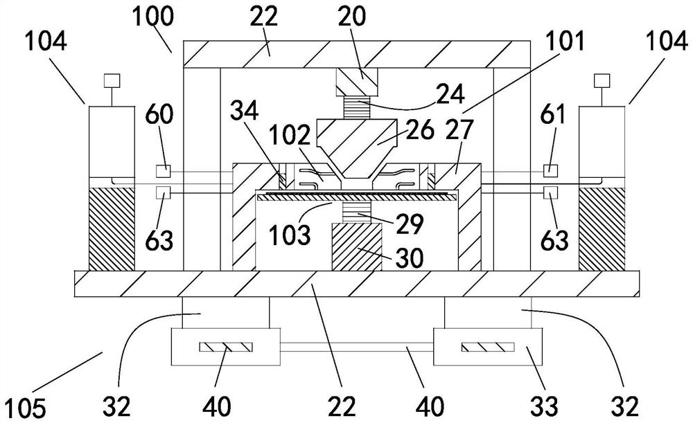
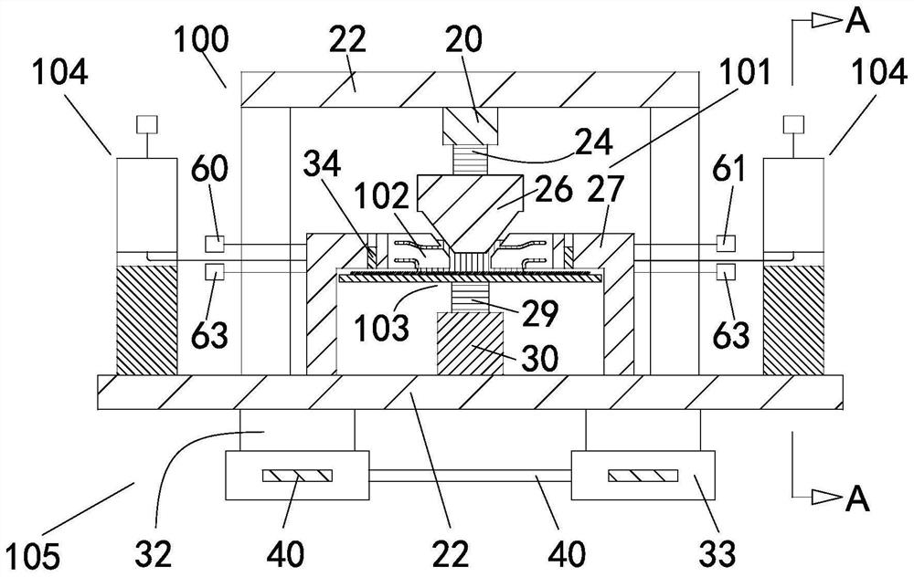
[0041] Figure 1-6 In the shown embodiment, a device for testing the mechanical properties of fluid system components includes a test bench frame 22, a first three-axis adjuster 20 is installed on the underside of the top of the test stand frame 22, and the first three-axis adjuster 20 Its lower end is fixedly connected with an uplink disturbance detection mechanism 101. The first three-axis adjuster 20 adjusts the plane orientation of the plane where the uplink disturbance detection mechanism 101 is located by adjusting the plane orientation of its own plane. Below the uplink disturbance detection mechanism 101 is a The main body mechanism 102 of the immersion unit and the downlink disturbance detection mechanism 103, the centers of the uplink disturbance detection mechanism 101, the main body mechanism 102 of the immersion unit and the downlink disturbance detection mechanism 103 are all located on the same center vertical connecting line, and the uplink disturbance detection...

Embodiment 2

[0050] Figure 1-6 In the shown embodiment, a fluid system component mechanical property testing system includes a data acquisition card 50, a data processing terminal 51 and the fluid system component mechanical property testing device 100 described in Embodiment 1, and the fluid system component mechanical property The various sensors set in the performance detection device 100 are connected to the data acquisition card 50 through external cables, and the signals collected by the sensors are transmitted to the data processing terminal 51 via the data acquisition card 50 through the external cables, and the others are the same as in Embodiment 1. same.

Embodiment 3

[0052] Figure 1-6 In the shown embodiment, a method for testing the mechanical properties of fluid system components includes the following testing steps:

[0053] A1. Debugging preparation steps before testing;

[0054] Through the first three-axis adjuster 20 and the second three-axis adjuster 30 described in Embodiment 1 or Embodiment 2, the upward disturbance detection mechanism 101 and the downward disturbance detection mechanism 103 are adjusted to be in the same vertical center as the main body mechanism 102 of the immersion unit. position on the straight line;

[0055] A2. Fluid system simulation formation steps before testing;

[0056] Through the fluid system component mechanical performance detection device 100 described in embodiment 1 or embodiment 2, by adjusting the liquid supply module 60, the liquid discharge module 61, the gas supply module 63 and the gas discharge module 62, the fluid with a steady state is simulated system;

[0057] A3. Carry out the d...


PUM


Abstract

The invention discloses a fluid system component mechanical property detection device, system and method. The device comprises a detection platform rack, an ascending disturbance detection mechanism is disposed at the top of the detection platform rack, and an immersion unit main body mechanism and a descending disturbance detection mechanism are disposed below the ascending disturbance detectionmechanism. A supporting base mechanism used for strengthening supporting and reducing external disturbance is installed at the bottom of the detection table rack, so that an effective simulation sceneof the fluid systems is established, and disturbance force or vibration mechanical property detection is conducted on components associated with the multiple fluid systems at the same time, and on the layout design of related sensors and flow paths. Therefore, inherent orientation and stress characteristics of fluid system components in a fluid system are reserved, and the situation that effective signals are excessively lost due to a transmission path or structure of disturbance signals under a complex structure is avoided; therefore, rapid and high-precision accurate measurement of the sensor on disturbance is achieved.

Description

technical field [0001] The invention relates to a mechanical property detection device of a fluid system component, a detection device, a detection system and a detection method for a mechanical property detection device of a fluid system component used in an immersion photolithography machine system. Background technique [0002] In the immersion lithography machine system, the immersion liquid is supplied and recovered in the immersion unit arranged between the projection objective lens and the substrate, so that the immersion unit between the projection objective lens and the substrate is filled and formed with a stable flow of fluid system. During the flow of the fluid system in the immersion unit, it will generate disturbance force to the projection objective lens, substrate, substrate table carrying the substrate, and the frame of the lithography machine. The diverter block next to the immersion unit is recycled to maintain the immersion unit. During the gas-liquid tw...

Claims


Application Information

Patent Timeline
IPC IPC(8): G01M10/00
CPCG01M10/00
Inventor 符文静王帅胡归熊永乐徐文苹徐宁陈文昱付新
Owner ZHEJIANG CHEER TECH CO LTD
Learn More