Battery pack manufacturing method

A manufacturing method and battery pack technology, which is applied in secondary battery manufacturing, battery assembly, final product manufacturing, etc., can solve the problem of uneven thickness of the adhesive layer of battery modules and casings, large differences in waterproof and protective effects, and inability to Meet the use requirements and other issues, and achieve the effects of quality control, convenient glue injection, and improved production efficiency

Inactive Publication Date: 2021-02-26
HENAN BENMA +1
View PDF6 Cites 4 Cited by
  • Summary
  • Abstract
  • Description
  • Claims
  • Application Information

AI Technical Summary

Problems solved by technology

[0004] However, in the manufacturing process of the above-mentioned battery, the upper case and the lower case are first welded and fixed to form a sealed case, and then the potting compound is injected into the sealed case. In fact, before the potting compound is injected, due to the welding of the case Due to factors such as the movement of the battery module, the position of the battery module in the casing may have changed, which will cause the thickness of the adhesive layer between the battery module and the casing to be uneven, some places are thin, some places are thick, so the formed The waterproof and protective effects of the products are relatively different, and some even cannot meet the requirements of use.
In addition, when injecting glue, there is only one glue filling hole and it is relatively small, so it takes a long time to fill the gap inside the entire shell, and the production efficiency is relatively low, and the glue injection process is blind injection, so it is impossible to grasp the internal situation. Not conducive to quality control

Method used


Image

  • Battery pack manufacturing method
  • Battery pack manufacturing method

Examples


Embodiment Construction

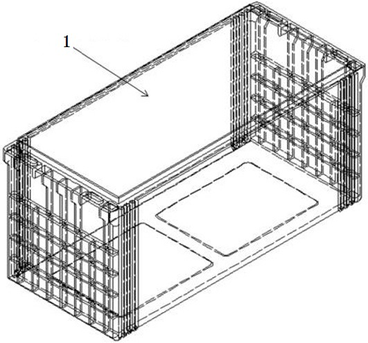
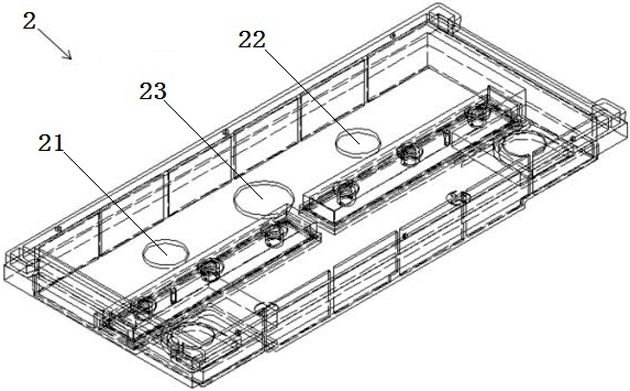
[0021] An embodiment of the battery pack manufacturing method in the present invention is: the battery pack manufacturing method is divided into two steps: the preparation of the casing and the sealing of the battery pack, wherein the preparation of the casing is as follows: figure 1 and figure 2 As shown, the upper case 2 and the lower case 1 need to be prepared, and two outlet holes for the positive lead-out wire and the negative lead-out wire of the battery pack need to be processed on the upper case 2, that is, the positive lead-out hole 21 and the Negative pole outlet hole 22. At the same time, it is also necessary to process a sampling hole 23 on the upper casing 2 for the sampling line of the battery pack to pass through. The sampling line is used to collect operating data such as voltage and temperature of the battery pack, so as to grasp the operation of the battery pack. The above-mentioned positive electrode outlet hole 21, negative electrode outlet hole 22 and sa...


PUM


Abstract

The invention provides a battery pack manufacturing method, and the method comprises the following steps: 1, putting an assembled battery module into a lower shell, and keeping a certain gap between the battery module and the peripheral side wall of the lower shell; 2, injecting a pouring sealant into a gap between the battery module and the lower shell, performing standing for a period of time, solidifying the pouring sealant, and achieving the pre-fixing of the battery module; 3, connecting the upper shell to the lower shell in a sealing manner to form a complete battery shell; 4, injectingthe pouring sealant into the battery shell from the sealant pouring hole in the upper shell until the pouring sealant fills the remaining space in the battery shell, and then performing standing for aperiod of time, so that the pouring sealant is cured. The battery module has the beneficial effects that after the battery module is placed in the lower shell, glue is injected firstly to realize pre-fixation, and the upper opening of the whole lower shell can be used as a glue injection hole, so that the glue injection is very convenient, and the production efficiency can be greatly improved; inaddition, the whole process is visible, quality control is facilitated, and the uniformity of the thickness of the peripheral adhesive layer is guaranteed.

Description

technical field [0001] The invention relates to a method for manufacturing a battery pack. Background technique [0002] As the new energy industry is recognized and applied by more and more people, the wind-solar hybrid street lamp market is also thriving. As an important energy storage device, the battery directly determines whether the street lamp can be used normally and its service life is long or short. At present, the most commonly used battery configuration for wind-solar hybrid street lamps is to put the assembled battery module into a special plastic housing for wind-solar hybrid street lamps, use a sealant to simply seal the housing and the upper cover, and then connect it to the power generation device and street lamps Finally, the battery is embedded under the light pole. [0003] In addition, there are other battery pack manufacturing methods in the prior art, such as an internal glue-filled battery disclosed in a Chinese utility model patent with the authori...

Claims


Application Information

Patent Timeline
IPC IPC(8): H01M10/04
CPCH01M10/0404Y02P70/50
Inventor 张媛媛古伟鹏邵杰张萌贾明正
Owner HENAN BENMA
Why Eureka
Try Eureka