Model cake making machine for food processing
A technology of food processing and modeling, which is applied in the direction of mixing/kneading with vertical installation tools, structural components of mixing/kneading machines, etc. It can solve the problems of time-consuming sending, inconsistent filling amount of cakes, poor sending effect, etc., and achieve The effect of reducing manpower consumption
- Summary
- Abstract
- Description
- Claims
- Application Information
AI Technical Summary
Problems solved by technology
Method used
Image
Examples
Embodiment 1
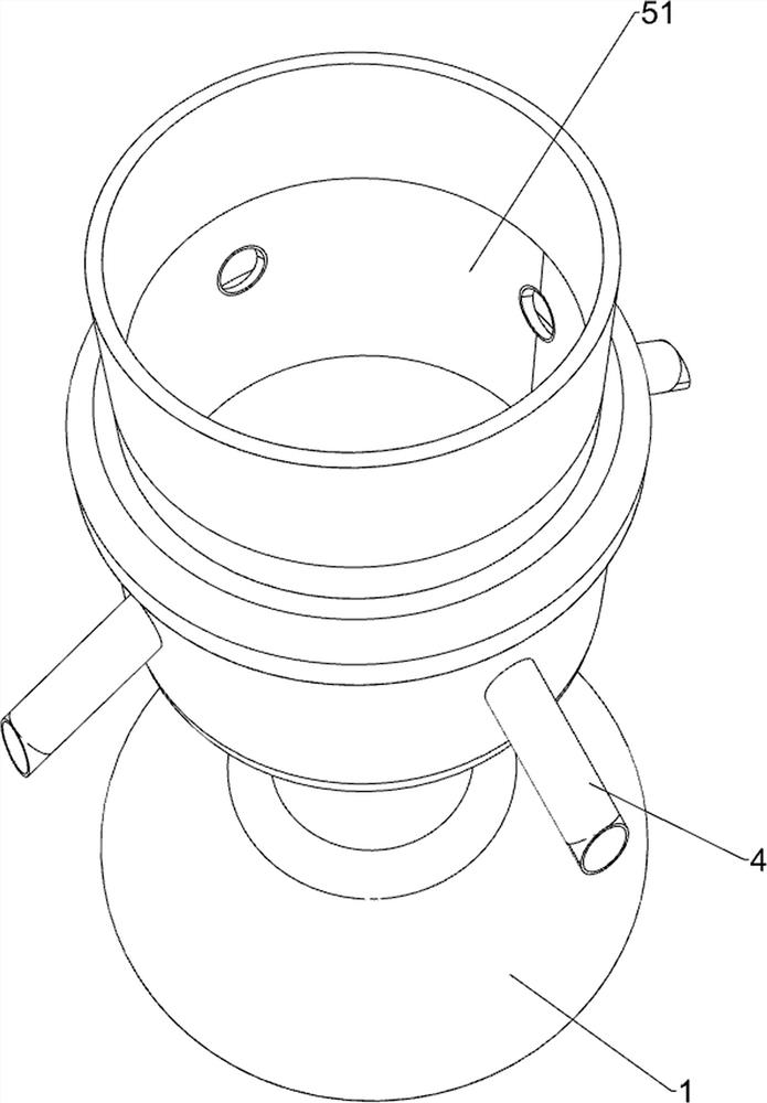
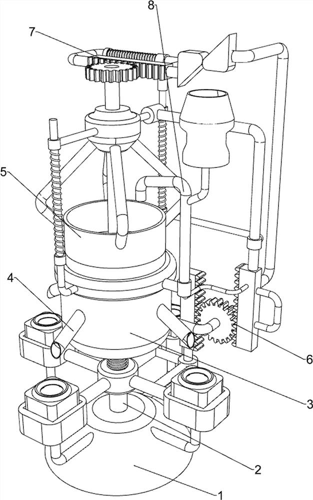
[0025] A model cake making machine for food processing, such as figure 1 and figure 2 As shown, it includes a base 1, a support column 2, a discharge frame 3, a discharge pipe 4, and a charging mechanism 5. The base 1 is provided with a support column 2, and the top of the support column 2 is provided with a discharge frame 3. The discharge frame 3 The upper part is evenly provided with four discharge pipes 4, and the upper part of the discharge frame 3 is provided with a charging mechanism 5.
[0026] People put a sufficient amount of raw materials for making cakes into the push-down charging mechanism 5, and manually push down the charging mechanism 5, so that the quantitative raw materials will flow into the model of the push-down charging mechanism 5 from the discharge pipe 4. , so as to process it into a model cake, and then let go to make the lower pressure charging mechanism 5 rise, thereby stopping the blanking, and repeat the above steps.
Embodiment 2
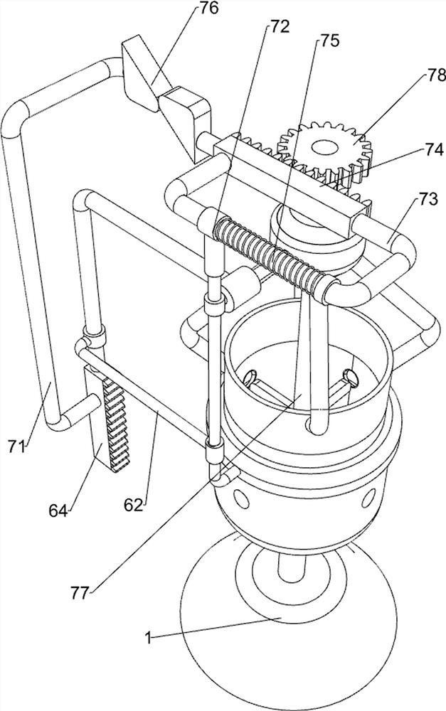
[0028] On the basis of Example 1, such as figure 2 and image 3 As shown, the charging mechanism 5 includes a material storage frame 51, a first positioning rod 52, a first sliding sleeve 53, a connecting pipe 54, a first spring 55, a connecting frame 56, a second spring 57 and a mold placement frame 58. A material storage frame 51 is slidably provided in the material pipe 4, first positioning rods 52 are provided on the front and rear sides of the upper part of the discharge pipe 4, and a first sliding sleeve 53 is slidably provided between the upper parts of the two first positioning rods 52. The middle part of the first sliding sleeve 53 is provided with a connecting pipe 54, the first springs 55 are wound on the two first positioning rods 52, the middle part of the support column 2 is slidingly provided with a mold placement frame 58, and the upper part of the support column 2 is wound with a second spring 57, the top of the second spring 57 is connected to the bottom of...
Embodiment 3
[0031] On the basis of Example 2, such as Figure 4 , Figure 5 , Image 6 and Figure 7 As shown, a feeding mechanism 6 is also included. The rear portion of the first sliding sleeve 53 is provided with a feeding mechanism 6. The feeding mechanism 6 is connected with the mold placement frame 58 and the first sliding sleeve 53. The feeding mechanism 6 includes a second A connecting rod 61, a second sliding sleeve 62, a second connecting rod 63, a first rack 64, a second rack 65, a third connecting rod 66, a first spur gear 67, a handle 68 and a push rod 69, the mold The right part of the placement frame 58 is connected with a first connecting rod 61, the bottom of the first positioning rod 52 on the rear side is provided with a second sliding sleeve 62, the rear portion of the first sliding sleeve 53 is provided with a second connecting rod 63, and the second connecting rod 63 Slidingly connected with the second sliding sleeve 62, the bottom of the second connecting rod 63 ...
PUM
 Abstract
Description
Claims
Application Information
 - R&D
- Intellectual Property
- Life Sciences
- Materials
- Tech Scout
- Unparalleled Data Quality
- Higher Quality Content
- 60% Fewer Hallucinations
Browse by: Latest US Patents, China's latest patents, Technical Efficacy Thesaurus, Application Domain, Technology Topic, Popular Technical Reports.
© 2025 PatSnap. All rights reserved.Legal|Privacy policy|Modern Slavery Act Transparency Statement|Sitemap|About US| Contact US: help@patsnap.com


