Cleaning equipment for mechanical parts

A technology for mechanical parts and cleaning equipment, which is applied in the field of mechanical parts cleaning, can solve the problems of reduced cleaning efficiency, waste of water resources, and time-consuming problems, so as to avoid blockage of water holes, improve cleaning efficiency, and improve cleaning effect Effect

Inactive Publication Date: 2021-03-02
CHANGZHOU COLLEGE OF INFORMATION TECH
View PDF8 Cites 3 Cited by
  • Summary
  • Abstract
  • Description
  • Claims
  • Application Information

AI Technical Summary

Problems solved by technology

The existing cleaning equipment for mechanical parts usually needs to be in a shutdown state when the parts are loaded and unloaded, which will not only consume a lot of time, but also greatly reduce the cleaning efficiency of the parts
The cleaning effect that the existing cleaning equipment can achieve is not good
After the cleaning water in the equipment is used for a long time, there will be too many stains in it, wh...

Method used


Image

  • Cleaning equipment for mechanical parts
  • Cleaning equipment for mechanical parts
  • Cleaning equipment for mechanical parts

Examples


Embodiment 1

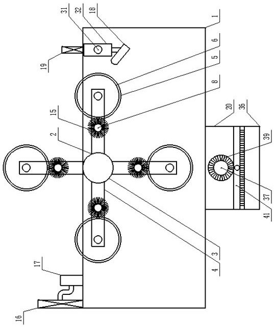
[0015] Example 1: see figure 1 , figure 2 , image 3 , Figure 4Now, a kind of cleaning equipment for mechanical parts provided by the present invention is described, which includes a cleaning body 1 designed with an upper end opening, and a cleaning mechanism 2 is provided in the cleaning body 1, and the cleaning mechanism 2 includes the length The top of the inner end wall on both sides of the direction is movably provided with a disc-shaped turret 3, a disc-shaped turret 3, and an equal arc on the outer circumferential end wall. Fixedly be provided with disc-shaped mounting frame 5, the cylindrical cleaning frame 6 that is all fixedly provided with between the disc-shaped mounting frame 5 along described cleaning body 1 length direction, the first that is provided with between the disc-shaped turret 3 The transmission shaft 7 and the support frame 4 are provided with the second transmission shaft 8 along the length direction of the cleaning body 1, the first driving pul...

Embodiment 2

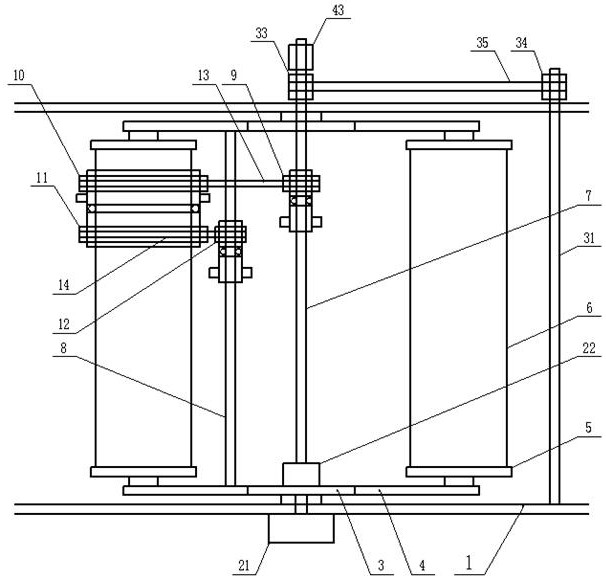
[0016] Example 2: see figure 1 , figure 2 , image 3 , a kind of cleaning equipment for mechanical parts provided by the present invention is now described, the top of the outer end wall on one side of the length direction of the cleaning body 1 is provided with a first motor 21, and the output shaft of the first motor 21 extends into the cleaning In the body 1, and its protruding end end is fixedly connected with the central portion of the disc-shaped turret 3, and the number of support frames 4 provided on the outer peripheral end wall of the disc-shaped mounting frame 5 is four, so The support frame 4 is arranged along the radial direction of the cross section of the disc-shaped mounting frame 5, and the disc-shaped turret 3 arranged near the position of the first motor 21 corresponds to the middle part of the end wall on the other side of the position of the first motor 21. A second motor 22 is provided, one end of the first transmission shaft 7 in the length direction ...

Embodiment 3

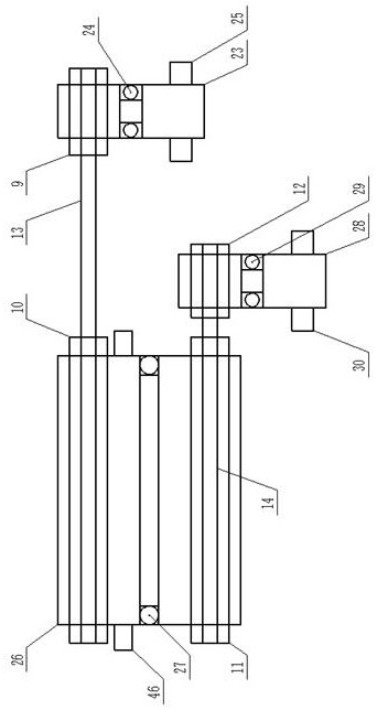
[0017] Embodiment 3: see figure 2 , image 3 , a kind of cleaning equipment for mechanical parts provided by the present invention is now described, the outside of the cylindrical cleaning frame 6 is sleeved on the second cylindrical transmission frame 26, and the inner diameter of the second cylindrical transmission frame 26 is larger than the The diameter of the outer end of the cross-section of the cylindrical cleaning frame 6, the second cylindrical drive frame 26 is provided with a second bearing-shaped connector between the inner end wall of the middle side in the length direction and the outer end wall of the cylindrical cleaning frame 6 27. The outer sides of the second cylindrical transmission frame 26 in the length direction are respectively covered with the first driven pulley 10 and the second driving pulley 11, and the outer end of one side of the second cylindrical transmission frame 26 is The second connecting cylinder 46 is evenly arranged on the wall with eq...


PUM


Abstract

The invention discloses cleaning equipment for mechanical parts, and relates to the field of mechanical part cleaning. The cleaning equipment comprises a cleaning machine body; a cleaning mechanism isarranged in the cleaning machine body; the cleaning mechanism comprises a disc-shaped rotating frame, a supporting frame, a disc-shaped mounting frame, a cylindrical cleaning frame, a first transmission shaft, a second transmission shaft, a first driving belt wheel, a first driven belt wheel, a second driving belt wheel, a second driven belt wheel, a first belt, a second belt and first bristles;a dust removal fan and a dust guide pipe are arranged at the upper end of one side of the cleaning machine body in the width direction; a sprinkler head and an air dryer are arranged at the upper endof the other side; and a flow guide filtering shell is arranged at the outer bottom of the cleaning machine body. According to the equipment, machine part loading and unloading, machine part pretreatment, machine part washing and machine part air drying can be integrated and can also be carried out at the same time, so that the machine part cleaning efficiency is greatly improved; efficient cleaning of parts is achieved, and the part cleaning effect is improved; and cleaning water is filtered and recycled, so that the water resource is saved while the environment is protected.

Description

technical field [0001] The invention relates to the field of cleaning mechanical parts, in particular to a cleaning device for mechanical parts. Background technique [0002] Dust and other impurities will inevitably adhere to mechanical parts during the production and processing process, which requires subsequent cleaning operations. When the existing cleaning equipment for mechanical parts is loaded and unloaded, the equipment usually needs to be in a shutdown state, which will not only consume a lot of time, but also greatly reduce the cleaning efficiency of the parts. The cleaning effect that existing cleaning equipment can realize is also not good. After the cleaning water in the equipment is used for a long time, there will be too many stains in it, which will greatly reduce the cleaning effect of the machine parts, and the direct discharge of cleaning water will not only cause environmental pollution, but also cause a lot of waste of water resources. The machine par...

Claims


Application Information

Patent Timeline
IPC IPC(8): B08B3/02B08B3/06B08B3/14B08B5/04B08B9/087B08B13/00F26B21/00
CPCB08B3/02B08B3/06B08B3/14B08B5/04B08B9/087B08B13/00F26B21/00
Inventor 夏小惠
Owner CHANGZHOU COLLEGE OF INFORMATION TECH
Why Eureka
Try Eureka