
Method and supporting mechanism suitable for machining large thin-wall frame ring part

A technology of parts processing and support mechanism, which is applied in the field of thin-walled parts processing, can solve problems such as difficult to guarantee dimensional accuracy, no measures taken for chatter, and affect processing quality, etc., to ensure accuracy, suppress surface quality deterioration, and suppress processing chatter Effect

Active Publication Date: 2021-03-02
SHANGHAI SPACE PRECISION MACHINERY RES INST
View PDF7 Cites 0 Cited by
  • Summary
  • Abstract
  • Description
  • Claims
  • Application Information

AI Technical Summary

Problems solved by technology

[0007] In view of the difficulty in ensuring dimensional accuracy and the deterioration of surface quality in the overall processing of large thin-walled frame ring parts, it is urgent to provide a process method that can effectively process large thin-walled end frames
[0008] Patent document CN109333092A discloses a fixture for an annular thin-walled part and a method for processing the thin-walled outer surface of the part. The step of the end face, the annular thin-walled part is placed on the step; at least three limit blocks, the limit blocks are evenly distributed around the circumference and fixed on the fixture support, one end of which is set on the fixture support The upper end surface of the seat, and the side of this end is in close contact with the inner ring surface of the annular thin-walled part; at least three pressing blocks, the pressing blocks and the limiting block are evenly spaced and fixed on the fixture support and one end of the pressing block presses the upper end surface of the annular thin-walled part, but no measures are taken for the vibration during the processing, which affects the processing quality

Method used


Image

  • Method and supporting mechanism suitable for machining large thin-wall frame ring part
  • Method and supporting mechanism suitable for machining large thin-wall frame ring part
  • Method and supporting mechanism suitable for machining large thin-wall frame ring part

Examples


Embodiment Construction

[0059] The present invention will be described in detail below in conjunction with specific embodiments. The following examples will help those skilled in the art to further understand the present invention, but do not limit the present invention in any form. It should be noted that those skilled in the art can make several changes and improvements without departing from the concept of the present invention. These all belong to the protection scope of the present invention.

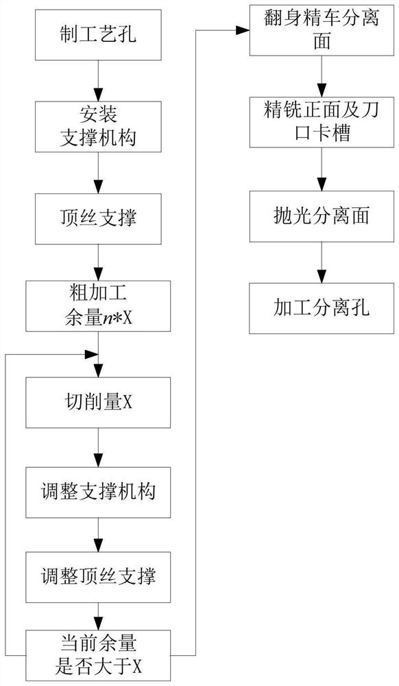
[0060] The invention provides a method suitable for processing large-scale thin-walled frame ring parts, which can simply and effectively ensure product accuracy, suppress surface quality deterioration and improve surface microscopic topography quality, such as figure 1 shown, including the following steps:

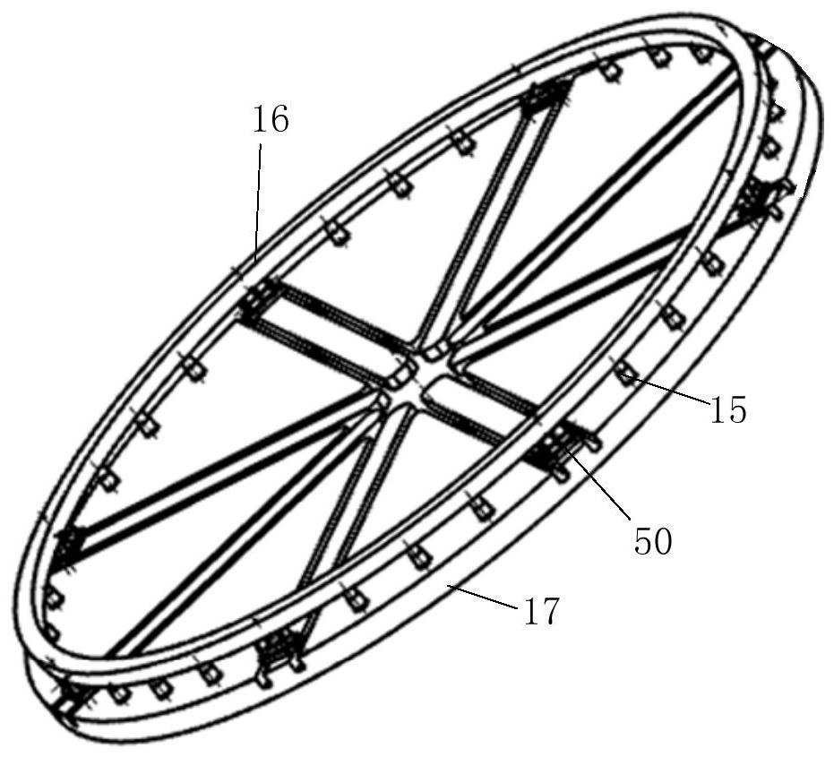
[0061] Firstly, rough machining is performed on the workpiece 24. The blank before rough machining is the forging ring fine material 16, and the threaded holes are used to install the threaded pin ...


PUM

PropertyMeasurementUnit
Thicknessaaaaaaaaaa

Abstract

The invention provides a method and supporting mechanism suitable for machining a large thin-wall frame ring part. The method comprises the following steps that S1, rough machining is conducted on a machined part, the rough machining procedure is split into n times, the cutting allowance of each time is set, and the supporting mechanism of the machined part is readjusted after each time of cuttingis completed; S2, the machined part is subjected to finish machining, and a filler filling measure is adopted; and S3, the machined workpiece is polished. According to the method, control measures including three aspects of guaranteeing the product precision, inhibiting surface quality deterioration and improving the surface microstructure quality are adopted for machining the large thin-wall frame ring part, product deformation is effectively controlled on the macroscopic level, and the separation interface precision is guaranteed; the generation of machining flutter is effectively inhibitedon the submicroscopic level, and the assembly precision is ensured; and in the microcosmic level, the surface quality and the optical reflectivity in the vacuum environment are improved, the qualityrisk of separation cold welding is reduced, the technological method is simple and effective, and the engineering application condition is achieved.

Description

technical field [0001] The invention relates to the technical field of processing thin-walled parts, in particular to a method and a supporting mechanism suitable for processing large-scale thin-walled frame ring parts. Background technique [0002] Large thin-walled parts are the key products of various aircraft in the aerospace field and an important component of the main frame of the structure. Due to the continuous pursuit of lightweight and high reliability, large structural parts are usually formed by forgings or castings as a whole. In order to achieve ideal structural efficiency, there are often a large number of thin-walled cavities, cantilever beams, ribs and other structures with extremely poor rigidity. Considering the extreme temperature in the deep space environment, there are extremely high requirements on the reflectivity and surface quality of the metal surface, so as to avoid damage to the internal instruments caused by the high temperature environment. At...

Claims


Application Information

Patent Timeline
IPC IPC(8): B23P15/00
CPCB23P15/00Y02P70/10
Inventor 周井文戚菊芳沈宏华黄久超徐爱杰刘星任培强
Owner SHANGHAI SPACE PRECISION MACHINERY RES INST
Learn More