Supercharge Your Innovation With Domain-Expert AI Agents!

U-shaped coal gasification waste heat boiler with spray cooling device and cooling method

A waste heat boiler, spray cooling technology, applied in the field of boilers, can solve the problems of exhaust gas temperature caused by burning of the heating surface in the waste heat heat exchange chamber, slag is easy to adhere, and affects the safe operation of the gasifier, etc.

Active Publication Date: 2022-03-11
HARBIN INST OF TECH
View PDF4 Cites 0 Cited by
  • Summary
  • Abstract
  • Description
  • Claims
  • Application Information

AI Technical Summary

Problems solved by technology

[0004] The present invention aims to solve the problem that the molten slag in the secondary gasification chamber of the existing coal gasification system is easy to adhere to the water cooling wall, forming large slag blocks, which block the horizontal flue when the slag blocks fall, and affect the safe operation of the gasifier; at the same time, the existing The high temperature of synthetic gas at the inlet of the waste heat exchange chamber of the coal gasification system leads to the burning of the heating surface in the waste heat heat exchange chamber and the high exhaust gas temperature, and then a U-shaped coal gasification waste heat boiler with a spray cooling device and a cooling method are proposed

Method used


Image

  • U-shaped coal gasification waste heat boiler with spray cooling device and cooling method
  • U-shaped coal gasification waste heat boiler with spray cooling device and cooling method
  • U-shaped coal gasification waste heat boiler with spray cooling device and cooling method

Examples


specific Embodiment approach 1

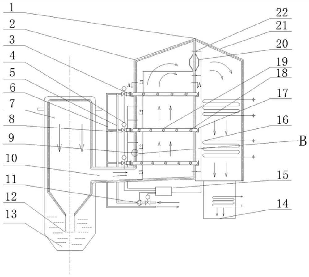
[0024] Specific implementation mode one: combine Figure 1-Figure 4 Describe this embodiment, a U-shaped coal gasification waste heat boiler with a spray cooling device described in this embodiment, which includes a waste heat boiler body 1, a gasification furnace body 7, a horizontal flue 10, and a gasification furnace slag outlet 12 and slag pool 13; waste heat boiler body 1 includes secondary gasification chamber 2 and waste heat heat exchange chamber 21, characterized in that: secondary gasification chamber 2 includes spray system, water supply system and control system; gasification furnace body 7 It communicates with the secondary gasification chamber 2, the gasification furnace slag outlet 12 is set in the slag pool 13, the waste heat heat exchange chamber 21 is set close to the secondary gasification chamber 2, and the gasification furnace body 7 and the secondary gasification chamber 2 pass through The horizontal flue 10 is connected, and the waste heat heat exchange ...

specific Embodiment approach 2

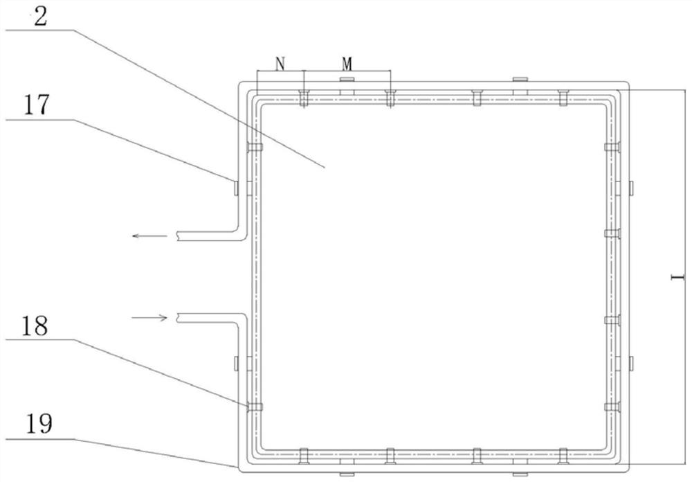
[0025] Specific implementation mode two: combination figure 1 and figure 2 Describe this embodiment, a U-shaped coal gasification waste heat boiler with a spray cooling device described in this embodiment, the spray system includes a plurality of connecting flanges 3, a plurality of brackets 17, a plurality of nozzles 18 and a plurality of spray Spray water pipe 19, the two ends of spray water pipe 19 are respectively equipped with a connecting flange 3, a plurality of spray water pipes 19 are installed on the secondary gasification chamber 2 from top to bottom, and the spray water pipe 19 is installed along the direction of how many A nozzle 18, and a spray water pipe 19 are installed on the outer wall of the water-cooled wall of the secondary gasification chamber 2 through a plurality of brackets 17. Other structures and methods are the same as those in Embodiment 1.

[0026] In this embodiment, the number of sprinkler water pipes 19 arranged from top to bottom is one to ...

specific Embodiment approach 3

[0027] Specific implementation mode three: combination figure 1 Describe this embodiment mode, a U-shaped coal gasification waste heat boiler with a spray cooling device described in this embodiment mode, the water supply system includes a water pump 11, a water inlet pipe 5 and a water outlet pipe 6, the water pump 11 is installed on the water inlet pipe 5, and the water inlet pipe The water pipe 5 communicates with the inlet end of the spray water pipe 19 , and the outlet end of the spray water pipe 19 communicates with the water outlet pipe 6 . Other structures and methods are the same as in the first embodiment.

[0028] Specific implementation mode four: combination figure 1 and image 3Describe this embodiment, a U-shaped coal gasification waste heat boiler with a spray cooling device described in this embodiment, the control system includes a DCS controller 15, a flow meter 4, a plurality of high-temperature thermocouples 9, a plurality of medium-temperature thermocou...


PUM


Abstract

A U-shaped coal gasification waste heat boiler with a spray cooling device and a cooling method. The present invention relates to a U-shaped coal gasification waste heat boiler. The present invention aims to solve the problem of easy adhesion of slag in the secondary gasification chamber of the existing coal gasification system On the water wall, large slag blocks are formed, and when the slag blocks fall, they block the horizontal flue and affect the safe operation of the gasifier; at the same time, the high temperature of the syngas at the inlet of the waste heat heat exchange chamber of the existing coal gasification system causes the heating surface of the waste heat heat exchange chamber The problem of burning loss and high exhaust gas temperature, the gasification furnace body is connected with the secondary gasification chamber, the slag outlet of the gasification furnace is set in the slag pool, the waste heat exchange chamber is set close to the secondary gasification chamber, the gasification furnace body is connected with the secondary gasification chamber The secondary gasification chamber is connected through a horizontal flue. There is a convection heating surface in the waste heat heat exchange chamber. The bottom of the convection heating surface is a synthesis gas outlet, and the top of the convection heating surface is a synthesis gas inlet. The spray system is installed in the secondary gasification chamber. On the outer wall of the water wall, the spray system and the water supply system are connected with the control system. The invention belongs to the field of boilers.

Description

technical field [0001] The invention relates to a U-shaped coal gasification waste heat boiler, in particular to a U-shaped coal gasification waste heat boiler with a spray cooling device and a cooling method, belonging to the field of boilers. Background technique [0002] Coal is the conventional energy with the largest reserves and the widest distribution in the world, and it is also an important strategic resource. Worldwide, coal reserves account for about 90% of the total reserves of various energy sources, and are widely used in industrial production fields such as iron and steel, electric power, and chemicals, as well as in residential areas. With the development of low-carbon economy and the intensification of environmental governance, coal as a fossil energy is facing more and more environmental pressure. Therefore, efficient and clean coal gasification technology is an inevitable strategic choice for the sustainable development of my country's economy and society....

Claims


Application Information

Patent Timeline
Patent Type & Authority Patents(China)
IPC IPC(8): C10J3/86
CPCC10J3/86Y02P20/129
Inventor 曾令艳谭紫莹路跃陈智超李争起
Owner HARBIN INST OF TECH
Features
  • R&D
  • Intellectual Property
  • Life Sciences
  • Materials
  • Tech Scout
  • Unparalleled Data Quality
  • Higher Quality Content
  • 60% Fewer Hallucinations
Learn More