Textile dip dyeing device

A textile and dyeing liquid technology, which is applied in the processing of textile material equipment configuration, textile and papermaking, and textile material processing, can solve the problems of unevenness, insufficient covering work speed, and low covering work efficiency, and achieve high work efficiency. Simple operation to complete different work requirements

Inactive Publication Date: 2021-03-02
陈爱珍
View PDF0 Cites 0 Cited by
  • Summary
  • Abstract
  • Description
  • Claims
  • Application Information

AI Technical Summary

Problems solved by technology

[0004] Aiming at the deficiencies of the prior art, the present invention provides a textile exhaust dyeing device, which solves the problems that the device will be uneven when the device is dipped, the speed of the device's covering work in the solvent is not enough, and the covering work efficiency is low.

Method used


Image

  • Textile dip dyeing device
  • Textile dip dyeing device
  • Textile dip dyeing device

Examples


Embodiment example 1

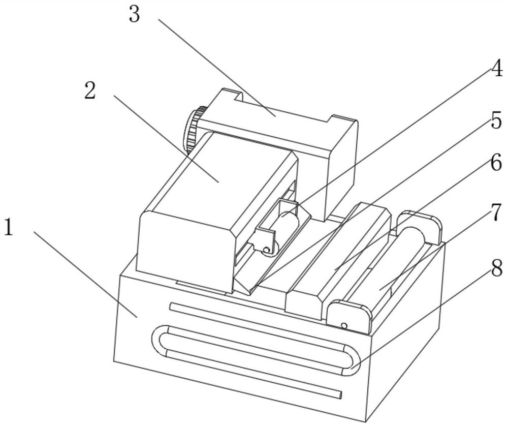
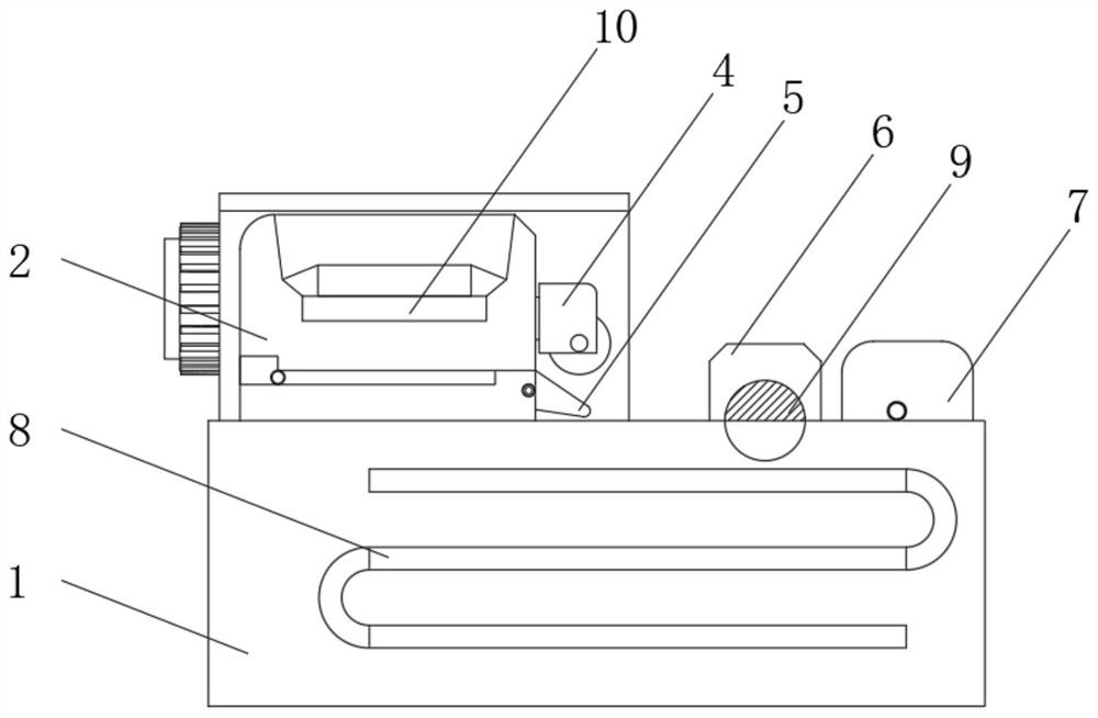
[0033] see Figure 1-2 , the present invention provides a technical solution: a textile exhaust dyeing device, including a printing and dyeing pool 1, a printing and dyeing post-treatment box 2 is arranged above the printing and dyeing pool 1, a control box 3 is arranged on the side of the printing and dyeing post-processing box 2, and a printing and dyeing post-processing box 2. A movable printing and dyeing auxiliary cylinder 4 is installed on the side above the printing and dyeing pool 1. A dipping and dyeing pool is provided inside the printing and dyeing pool 1. A dipping liquid mixing device 6 is arranged on the top of the printing and dyeing pool 1. The top of the printing and dyeing pool 1 is far away from the post-printing and dyeing treatment box 2. A feed roller 7 is installed on one side, and a feed adjustment plate 5 is installed below the feed port of the post-printing and dyeing treatment box 2. 5 is located under the movable printing and dyeing auxiliary cylind...

Embodiment example 2

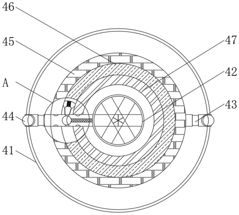
[0035] see Figure 1-5, on the basis of the implementation case 1, the present invention provides a technical solution: the movable printing and dyeing auxiliary cylinder 4 includes a cylinder body 41, a central shaft 42 is arranged inside the cylinder body 41, and an external storage liquid collar 45 is arranged inside the cylinder body 41. The middle storage liquid collar 46 and the storage liquid collar 47, the drum body 41 is provided with a through pipe 43 inside, the through pipe 43 runs through the external storage liquid collar 45, the middle storage liquid collar 46 and the memory liquid collar 47, and the through pipe The outer contact roller 44 is installed on the outer side of 43, and the inside of the movable printing and dyeing auxiliary cylinder 4 adopts a plurality of liquid storage inner collars, and different solvents are added inside. When the movable printing and dyeing auxiliary cylinder 4 has different rotation speeds, the device will produce With differe...

Embodiment example 3

[0040] see Figure 1-7 , on the basis of the implementation case 1 and the implementation case 2, the present invention provides a technical solution: the mixing mechanism 9 includes a side mounting seat 91, and a central shaft 92 and an outer spiral mixing frame 93 are installed between the side mounting seats 91 , the central axis 92 is located at the inner side of the outer helical wire mixing frame 93, a chute mounting frame is installed outside the central axis 92, an outer movable frame 94 is installed on the outer side of the chute mounting frame, and a centrifugal connector 96 is installed between the outer movable frames 94. Elastic buffer rods 95 are installed between the movable frames 94 .

[0041] The outer spiral wire mixing frame 93 is provided with three groups, and the gap between the three groups of outer spiral wire mixing racks 93 is smaller than the gap between the outer spiral wire mixing frame 93's own helix, and the mixing mechanism 9 of the device is i...


PUM


Abstract

The invention discloses a textile dip dyeing device which comprises a printing and dyeing pond, wherein a printing and dyeing post-treatment box is arranged above the printing and dyeing pond, a control box body is arranged on the side edge of the printing and dyeing post-treatment box, a movable printing and dyeing auxiliary roller is mounted in a position, above the printing and dyeing pond, atthe side edge of the printing and dyeing post-treatment box, a dip dyeing pond is arranged in the printing and dyeing pond, a dip dyeing liquid mixing device is arranged on the top of the printing anddyeing pond, a feeding roller is mounted on the side, far away from the printing and dyeing post-treatment box, of the top of the printing and dyeing pond, and a feeding positioning plate is mountedbelow a feeding port of the printing and dyeing post-treatment box. The invention relates to the technical field of textile. The textile dip dyeing device can solve the problem of performing die dyeing and conveying the printing and dyeing roller quickly. A textile fabric will be dried primarily by a printing and dyeing drier above, so that follow-up processing is facilitated. The feeding positioning plate of the device can be used for adjusting the angle, so that whether the textile fabric passing through is in tight contact with the movable printing and dyeing auxiliary roller above or not is achieved.

Description

technical field [0001] The invention relates to the technical field of textiles, in particular to a textile dipping device. Background technique [0002] The general term for weaving, spinning and weaving. Ancient Chinese textile and printing and dyeing technology has a very long history. As early as in the primitive society, in order to adapt to climate change, the ancients knew how to use local materials, use natural resources as raw materials for textile and printing and dyeing, and make simple textile tools. Until today, our daily clothing, some daily necessities and artworks are all products of weaving and printing and dyeing technology. Printing and dyeing, also known as dyeing and finishing, is a processing method and a general term for dyeing, printing, finishing, washing, etc. In the traditional printing and dyeing process, when the printing and dyeing machine is used to process the printed and dyed gray cloth, the device will be unevenly dyed, the speed of the de...

Claims


Application Information

Patent Timeline
Patent Type & Authority Applications(China)
IPC IPC(8): D06B3/10D06B23/20D06B23/22D06B15/00D06B23/02
CPCD06B3/10D06B15/00D06B23/02D06B23/20D06B23/205D06B23/22
Inventor 陈爱珍
Owner 陈爱珍
Why Eureka
Try Eureka