Embedded track structure of high-speed railway

An embedded track, high-speed railway technology, applied in the direction of tracks, roads, ballast layers, etc., can solve the problems of increasing line maintenance costs, increasing rail maintenance costs, environmental vibration and noise, etc., to reduce maintenance costs, anchoring The force is not easy to change and the train runs smoothly

Pending Publication Date: 2021-03-02
CHINA RAILWAYS CORPORATION +1
View PDF0 Cites 1 Cited by
  • Summary
  • Abstract
  • Description
  • Claims
  • Application Information

AI Technical Summary

Problems solved by technology

There are a large number of gaps between the rail and the rail groove, and the following problems exist: 1. The impact load of the train passing by is buffered by the backing plate and the discrete compression elastic strip, which belongs to the discrete point type buffer, and its buffer capacity is limited. Environmental vibration and noisy
2. The track is connected and supported by fasteners, which is also a discrete and point structure; in addition, the elastic force of the elastic bars at each connection point depends on the pre-tightening torque of the anchor bolts, and the pre-tightening force of the anchor bolts at each point on the track is difficult. Keep consistent, which leads to large changes in the support stiffness of the rail, poor smoothness, and it is easy to cause corrugation in the longitudinal direction of the rail (irregular wavy wear on the rail along the longitudinal surface), which further causes strong vibration and noise. Increased rail maintenance costs
3. The anchor bolts and elastic strips on the track form a dynamic balanced pre-tightening state. During use, the pre-tightening force tends to deviate, resulting in the need for frequent replacement and maintenance, which increases the maintenance cost of the line

Method used


Image

  • Embedded track structure of high-speed railway
  • Embedded track structure of high-speed railway
  • Embedded track structure of high-speed railway

Examples


Embodiment

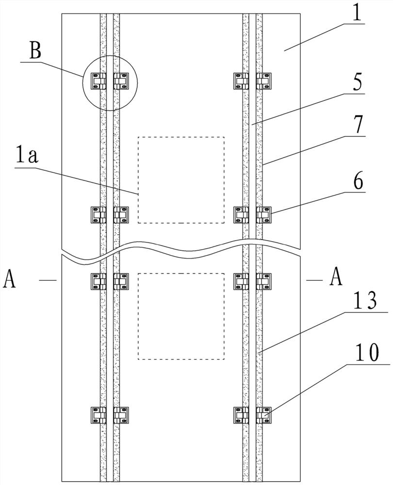
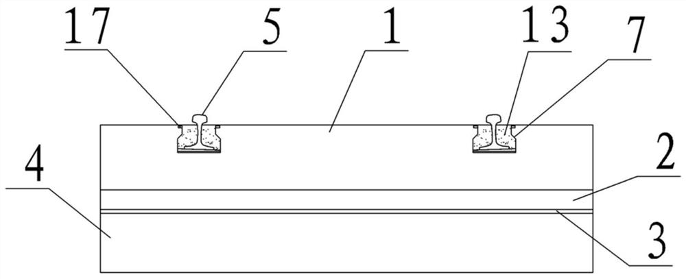
[0028] figure 1 - Figure 5 As shown, a specific embodiment of the present invention is: a high-speed railway embedded track structure, comprising a base 4 and a track slab 1 above the base 4, characterized in that:

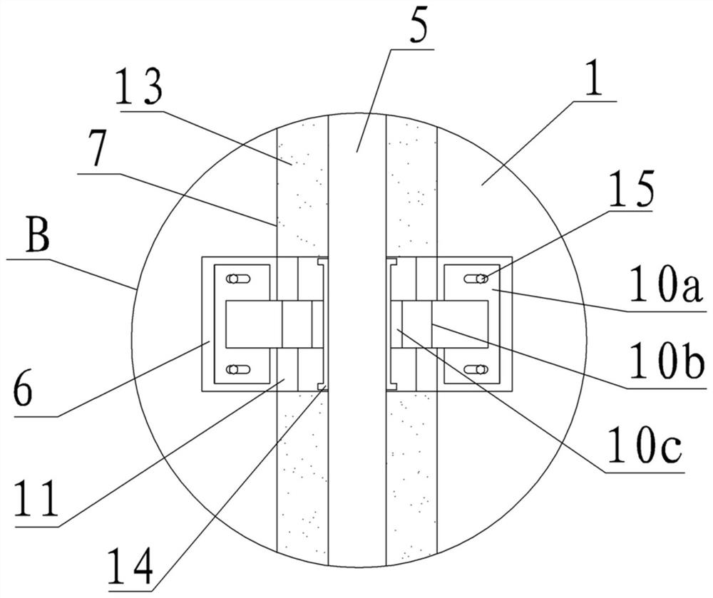
[0029] The track slab 1 is prefabricated from reinforced concrete. There are two rail bearing grooves 7 longitudinally and symmetrically distributed on the track slab 1. The cross section of the rail bearing groove 7 is bottle-shaped. The height-adjusting backing plate 12, the elastic backing plate 11 and the rail 5 are laid, the width of the height-adjusting backing plate 12 and the elastic backing plate 11 is equal to the width of the rail bearing groove 7, the width of the rail 5 is smaller than the width of the rail bearing groove 7, and the rail The rail top of 5 is higher than the bearing groove 7;

[0030] Figure 5 and Figure 1-4 It is shown that the rail bearing groove 7 is equidistantly provided with rail adjustment grooves 6 having a width greater...


PUM


Abstract

An embedded track structure of a high-speed railway comprises a base and a track plate on the base, and is characterized in that the track plate is formed by prefabricating reinforced concrete, and aheight adjusting base plate, an elastic base plate and a steel rail are arranged in two track bearing grooves in the track plate from bottom to top; track adjusting grooves are longitudinally formed in the track bearing grooves at equal intervals; track adjusting pieces on the two sides of the steel rail in the track adjusting grooves are fixed to the bottoms of the track adjusting grooves throughanchor bolts; damping blocks are embedded between the front hammers of the track adjusting pieces and the rail webs of the steel rails; polyurethane filling bodies are filled between the track bearing grooves outside the track adjusting grooves and the steel rails; the bottom surface of the track plate is connected with a cast-in-place self-compacting mortar layer; and protrusions on the top faceof the self-compacting mortar layer are matched with grooves in the bottom face of the track plate, and an isolation layer is arranged between the bottom face of the self-compacting mortar layer andthe prefabricated base. The track structure can greatly reduce environmental noise, and reduce corrugation of steel rails and maintenance of anchor bolts, and track maintenance is convenient and low in cost; and batch and mechanical production and automatic laying of the tracks can be realized, so that the high-speed railway lines are convenient and quick to lay.

Description

technical field [0001] The invention relates to a track structure for a high-speed railway. Background technique [0002] High-speed railway has become the inevitable trend and practical need of the development of my country's railway system. In order to meet the safety of passenger train operation and the comfort of passengers, the railway track must have high smoothness and high stability. The embedded ballastless track structure has good structural stability, stability, durability, less maintenance, economical and other technical characteristics, so it has been widely used in high-speed railways at home and abroad. [0003] The embedded ballastless track structure is composed of discrete (at a certain distance) fasteners that press the rails into the rail grooves of the cast-in-place unit plate groups. The fastener is mainly composed of anchor bolts on the side of the rail, compression clips and multiple backing plates at the bottom of the rail. There are a large numbe...

Claims


Application Information

Patent Timeline
Patent Type & Authority Applications(China)
IPC IPC(8): E01B1/00E01B9/68E01B19/00
CPCE01B1/00E01B9/68E01B19/00
Inventor 赵国堂魏峰杨国涛韩健何远鹏陈宗平
Owner CHINA RAILWAYS CORPORATION
Why Eureka
Try Eureka