
Optical fiber cable with long service life

A fiber optic cable, life-span technology, applied in the direction of light guide, optics, optical components, etc., can solve the problems of the internal optical fiber not playing a good role in protection, the popularity of optical fiber, low maintenance cost, easy to be bitten by animals, etc. Good protection effect, good fire protection effect, good effect of preventing animal bites

Active Publication Date: 2021-03-02
SHENZHEN SDG INFORMATION CO LTD
View PDF5 Cites 2 Cited by
  • Summary
  • Abstract
  • Description
  • Claims
  • Application Information

AI Technical Summary

Problems solved by technology

[0004] In order to overcome the above-mentioned defects of the prior art, the present invention provides an optical fiber cable with a long service life, which solves the problem that most optical fibers are placed on the ground before being laid, and are easily bitten by animals and crushed by vehicles, etc. Exposure to the environment for a long time after laying causes the outer protection of the cable to break, and the current optical fiber is constantly pulled during laying. If the outer protection slips, the internal optical fiber is prone to breakage due to force , does not have a long-term use, and does not have a good protection for the internal optical fiber, resulting in a high investment in the popularity of the optical fiber and the maintenance cost after laying

Method used


Image

  • Optical fiber cable with long service life
  • Optical fiber cable with long service life
  • Optical fiber cable with long service life

Examples


Embodiment Construction

[0029] The technical solution of this patent will be further described in detail below in conjunction with specific embodiments.

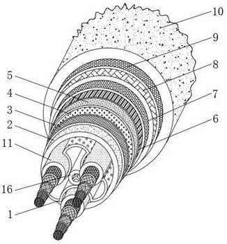
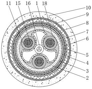
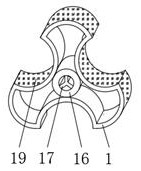
[0030] Such as Figure 1-7As shown, the present invention provides a technical solution: a fiber optic cable with high service life, including a bracket 1, the material of the bracket 1 is a tough steel plate, and the difference between the diameter of the inner wall of the limiting groove 19 and the surface diameter of the deformable layer 11 3 mm, by setting the bracket 1, the bracket 1 can maintain a stable protection for the optical fiber 15 during use, and at the same time can maintain a stable supporting effect. The bracket 1 is a tough steel plate, so that it can maintain the It has good toughness and can be reset in time after the stress is over. By setting the limit groove 19, the limit groove 19 can protect the optical fiber 15 very well, and at the same time, it can spread the pressure evenly and make the pressure change. form a clampin...


PUM


Abstract

The invention discloses an optical fiber cable with long service life, and belongs to the technical field of optical fiber cables. The optical fiber cable comprises a support frame, a compression-resistant layer is arranged on the surface of the support frame, an elastic damping layer is arranged on the surface of the compression-resistant layer, a water closing layer is arranged on the surface ofthe elastic damping layer, and a tensile layer is arranged on the surface of the water closing layer. According to the optical fiber cable with the long service life, through arrangement of a deformation layer and a separation layer, when the surface of the deformation layer is subjected to uniform extrusion force of the limiting grooves, the surface of the deformation layer starts to be gradually flattened, so that a very good supporting effect can be achieved after external protection and buffering, and stable protection of internal optical fibers can be kept; the deformation layer is madeof fluororesin, the surface of the deformation layer is smooth, then the inner walls of the limiting grooves are shrunk to a certain threshold value, the deformation layer in the limiting grooves canslide out under the action of extrusion force, meanwhile, the deformation layer extrudes a plurality of external protectors to deform after being buffered by the filling layer, and the limiting grooves can stably protect the optical fibers.

Description

technical field [0001] The invention belongs to the technical field of optical fiber cables, in particular to an optical fiber cable with long service life. Background technique [0002] A fiber optic cable is a communication cable consisting of two or more glass or plastic optical fiber cores within a protective cladding covered by a plastic PVC outer sleeve. Signal transmission along the internal optical fiber typically uses infrared, dielectric waveguide that transmits light waves. Optical fiber is a kind of fiber composed of two layers of transparent media in concentric circles. The most widely used dielectric material is quartz glass (SiO2). The inner medium, called the core, has a higher refractive index than the outer medium (called the cladding). The refractive index of the core or cladding is adjusted by doping germanium, phosphorus, fluorine, boron and other impurities in the quartz glass. The transmission wavelength of optical fiber for communication is mainly...

Claims


Application Information

Patent Timeline
Patent Type & Authority Applications(China)
IPC IPC(8): G02B6/44
CPCG02B6/4432G02B6/443G02B6/4436G02B6/4427G02B6/4407G02B6/44384
Inventor 高松
Owner SHENZHEN SDG INFORMATION CO LTD
Learn More