Rotor, motor, compressor and refrigeration equipment

A rotor and rotor core technology, applied in the field of compressors, can solve problems affecting customers' use, etc., and achieve the effects of improving the air gap magnetic field waveform, increasing back EMF, and improving user experience.

Active Publication Date: 2021-03-02
ANHUI MEIZHI PRECISION MFG
View PDF10 Cites 0 Cited by
  • Summary
  • Abstract
  • Description
  • Claims
  • Application Information

AI Technical Summary

Problems solved by technology

The vibration will be transmitted to the pipeline of the air conditioning system, causing resonance and affecting the use of customers

Method used


Image

  • Rotor, motor, compressor and refrigeration equipment
  • Rotor, motor, compressor and refrigeration equipment
  • Rotor, motor, compressor and refrigeration equipment

Examples


Embodiment 1

[0085] According to an embodiment of the present invention, in addition to the features defined in the above embodiments, preferably: on the section of the rotor core 2 perpendicular to the rotation axis of the rotor, the diameter of the circle where any point on the wall surface of the recessed part 6 is the same as that of the rotor The diameter ratio is less than 1 and greater than or equal to 0.985.

[0086] Further, on a section perpendicular to the rotation axis of the rotor, the diameter of the rotor is the line between any two points on the outer peripheral wall of the rotor core 2 passing through the line of the axis of the rotor, and any wall surface of the recessed portion 6 The circle where one point is located is a circle whose radius is the distance between any point on the wall surface of the recessed portion and the axis of the rotor, and the axis of the rotor is the center of the circle.

[0087] Preferably, the ratio of the diameter of the circle at the point...

Embodiment 2

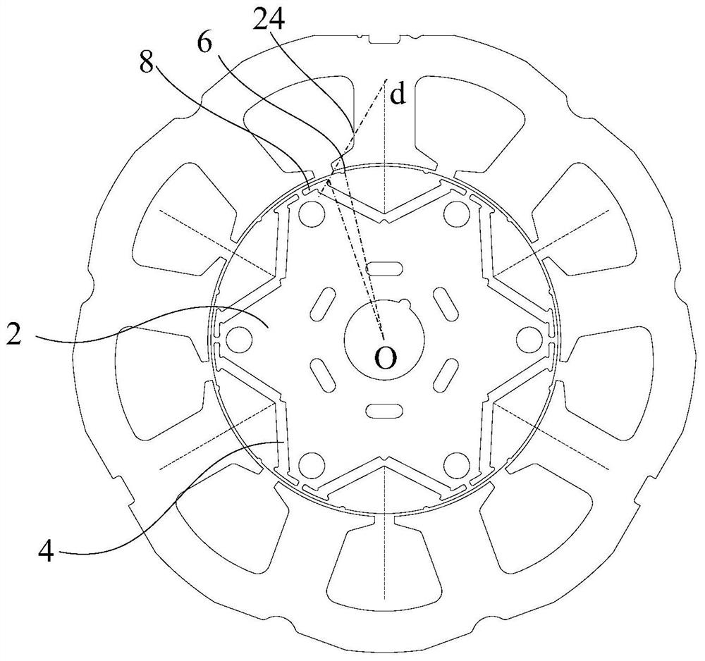
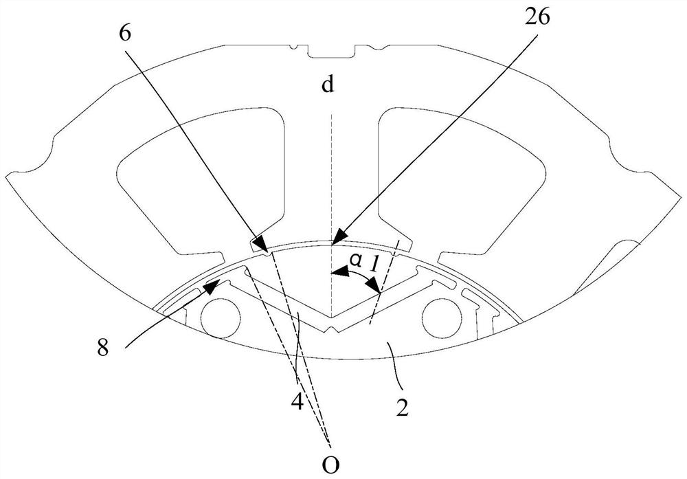
[0097] Preferably, as Figure 13 As shown, the end of the gap groove away from the arched portion 22 extends from the end of the permanent magnet to the q-axis direction, wherein the extending direction 24 of two adjacent d-axes is defined as the q-axis.

[0098] Preferably, as Figure 12 As shown, the rotor is used in a motor, and the motor also includes a stator. The stator includes a stator core 20 and a tooth portion arranged on the inner wall of the stator core 20. The minimum distance between two arched portions 22 in the same magnetic pole is D1, along the circumferential direction of the rotor, the width of the side of the teeth facing the rotor is D2, and D1 is greater than D2.

[0099] In this embodiment, the end of the gap groove away from the arched portion 22 extends from the end of the permanent magnet to the q-axis direction, which can improve the magnetic isolation effect of the gap portion. The motor also includes a stator, and the rotor is rotatably connect...

Embodiment 3

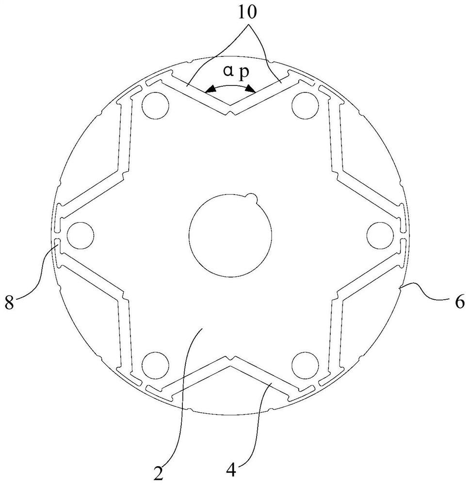
[0103] Such as Figure 5 to Figure 10 As shown, according to an embodiment of the present invention, in addition to the features defined in any of the above embodiments, preferably: there are multiple mounting slots 4, and the multiple mounting slots 4 are distributed along the circumferential direction of the rotor core 2; Along the circumferential direction of the rotor core 2 , the pole-to-pole width H between adjacent mounting slots 4 is greater than or equal to 0.6 mm and less than 1.2 mm.

[0104] In this example, if Figure 5 As shown, too small inter-pole width H between adjacent mounting slots 4 will reduce the mechanical strength, and too large inter-electrode width H between adjacent mounting slots 4 will reduce the back EMF and reduce the power density of the motor. Therefore, selecting the width H between poles to be greater than or equal to 0.6mm and less than 1.2mm can meet the structural strength of the motor while satisfying a certain amount of flux leakage. ...


PUM


Abstract

The invention provides a rotor, a motor, a compressor and refrigeration equipment. The rotor comprises: a rotor iron core, wherein the rotor iron core is provided with a plurality of mounting grooves,the peripheral wall of the rotor iron core is recessed towards the rotation axis direction of the rotor to form a recessed part, and the recessed part is located at one side, deviating from the rotation axis of the rotor, of each mounting groove; permanent magnets arranged in the mounting grooves to form a magnetic pole; and gap grooves which are formed in the rotor iron core, are positioned at the end parts of the mounting grooves, are communicated with the mounting grooves, and protrude towards the d-axis direction to form arching parts. The arching parts are located at one side, deviatingfrom the d axis, of a connecting line between the rotating axis of the rotor and any point on the wall surface of the concave part, the arching parts extend from the gap groove to the d axis direction, in any magnetic pole, a first intersection point is formed between the d axis and the peripheral wall of the rotor core, and the extending direction of the arching part is far away from the first intersection point. The rotor provided by the invention can improve the waveform of an air-gap magnetic field, can effectively reduce the vibration noise of the motor, and improves the noise hearing.

Description

technical field [0001] The invention relates to the technical field of compressors, in particular to a rotor, a motor, a compressor and a refrigeration device. Background technique [0002] In the existing rotary DC variable frequency compressors using motors, the motors generally use built-in permanent magnet motors. For the rotor of this type of motor, the harmonics of the air gap magnetic field are very rich, which is prone to generate large vibration noise and affect sense of hearing. In order to take the lead in compressor products, it is necessary to provide compressor motors with lower noise and more comfort. In recent years, the industry tends to design motors with higher power density, so the vibration and noise of motors are more prominent. The vibration will be transmitted to the pipeline of the air conditioning system, causing resonance and affecting the use of customers. Contents of the invention [0003] The present invention aims to solve at least one of t...

Claims


Application Information

Patent Timeline
Patent Type & Authority Applications(China)
IPC IPC(8): H02K1/27H02K1/14H02K21/02H02K29/03
CPCH02K1/14H02K1/2766H02K21/028H02K29/03H02K2213/03
Inventor 徐飞邱小华江波
Owner ANHUI MEIZHI PRECISION MFG
Why Eureka
Try Eureka