
nmos power tube drive circuit

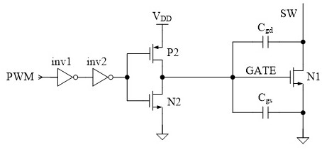
A technology for driving circuits and power tubes, applied in circuits, output power conversion devices, transistors, etc., can solve the problems of difficulty in reducing and large turn-off delay of NMOS power tubes, and achieve the effect of reducing the gate voltage drop time.

Active Publication Date: 2021-04-09
SHANGHAI NATLINEAR ELECTRONICS CO LTD +1
View PDF3 Cites 0 Cited by
  • Summary
  • Abstract
  • Description
  • Claims
  • Application Information

AI Technical Summary

Problems solved by technology

[0006] In view of the above-mentioned shortcomings of the prior art, the purpose of the present invention is to provide an NMOS power transistor drive circuit, which is used to solve the problem that the turn-off delay of the NMOS power transistor is relatively large and difficult to reduce in the prior art

Method used


Image

  • nmos power tube drive circuit
  • nmos power tube drive circuit
  • nmos power tube drive circuit

Examples


Embodiment Construction

[0039] Embodiments of the present invention are described below through specific examples, and those skilled in the art can easily understand other advantages and effects of the present invention from the contents disclosed in this specification. The present invention can also be implemented or applied through other different specific implementation modes, and various modifications or changes can be made to the details in this specification based on different viewpoints and applications without departing from the spirit of the present invention.

[0040] see Figure 1 to Figure 6 It should be noted that the diagrams provided in this embodiment are only schematically illustrating the basic concept of the present invention, although the diagrams only show components related to the present invention rather than the number and shape of components in actual implementation and size drawing, the shape, quantity and proportion of each component can be changed arbitrarily during actual...


PUM


Abstract

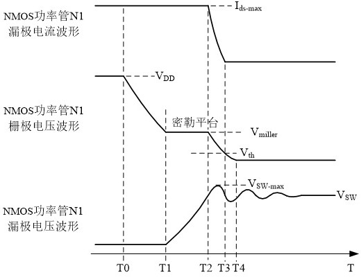
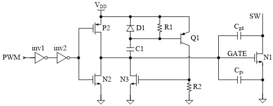
The invention provides an NMOS power transistor driving circuit, which is used to connect and control the working state of the NMOS power transistor. The first diode of the input terminal PMOS transistor and the input terminal NMOS transistor, the switch NMOS transistor, the first capacitor, the first resistor, the first triode and the second resistor. The present invention not only effectively reduces the gate voltage of the NMOS power transistor by reducing the duration of the T1A-T1 stage, T2-T3 stage and T3-T4 stage in the process of decreasing the grid voltage of the NMOS power transistor without reducing the duration of the T1-T2 stage. The voltage drop time, compared with the existing drive circuit, will not bring about the problems of increased overshoot of the drain voltage of the power tube and increased electromagnetic interference.

Description

technical field [0001] The invention relates to the field of integrated circuit design and application, in particular to an NMOS power tube drive circuit. Background technique [0002] The NMOS power transistor is a commonly used power transistor. It is widely used in various switching power supply management circuits due to its high reliability and high cost performance. [0003] At present, the NMOS power transistor generally needs to use a driving circuit to control the working state of the NMOS power transistor by controlling its gate voltage, so that the NMOS power transistor can switch between an off state and an on state. [0004] However, there is a delay in the turn-off process of the NMOS power tube, and there are parasitic capacitances between the gate and the drain, and between the gate and the drain in the power tube. How to quickly turn off the NMOS power tube and reduce the time-consuming turn-off stage has Become an important index to improve the performance...

Claims


Application Information

Patent Timeline
Patent Type & Authority Patents(China)
IPC IPC(8): H02M1/08H03K17/041
CPCH02M1/08H03K17/04106
Inventor 夏虎刘桂芝吴春达
Owner SHANGHAI NATLINEAR ELECTRONICS CO LTD
Learn More