Low-impact hinge unfolding mechanism

A deployment mechanism and low-impact technology, applied in motor vehicles, mechanical equipment, spring/shock absorber design features, etc., can solve the problem of unfavorable reliability of satellite extravehicular mechanisms, unstable antenna performance, and difficulty in antenna excitation and rapid consumption. To avoid problems such as dispersion, to achieve the effect of compact design, reduced deployment speed, and reduced impact

Active Publication Date: 2021-03-05
SHANGHAI RADIO EQUIP RES INST
View PDF11 Cites 0 Cited by
  • Summary
  • Abstract
  • Description
  • Claims
  • Application Information

AI Technical Summary

Problems solved by technology

However, with the increase in the size of the satellite antenna and the reduction in the quality of the antenna, the traditional hinge deployment mechanism has the disadvantage of excessive impact at the end of the deployment action.
Due to the lack of resistance in the space, it is difficult to quickly dissipate the vibration of the antenna caused by a large impact, which may easily cause the instability of the antenna's performance. Excessive instantaneous impact may damage the weak support rods on the antenna, causing the antenna to fail. This is detrimental to the reliability of the entire satellite extravehicular mechanism

Method used


Image

  • Low-impact hinge unfolding mechanism
  • Low-impact hinge unfolding mechanism
  • Low-impact hinge unfolding mechanism

Examples


Embodiment Construction

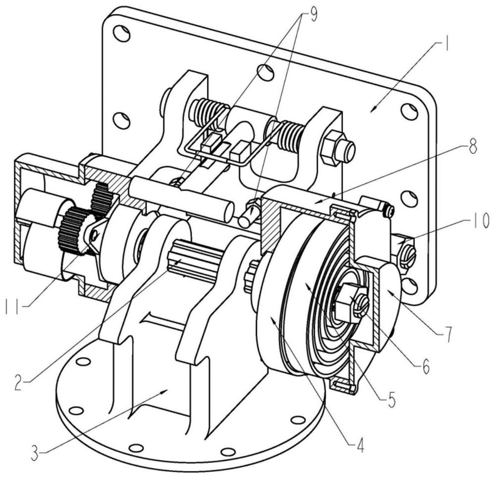
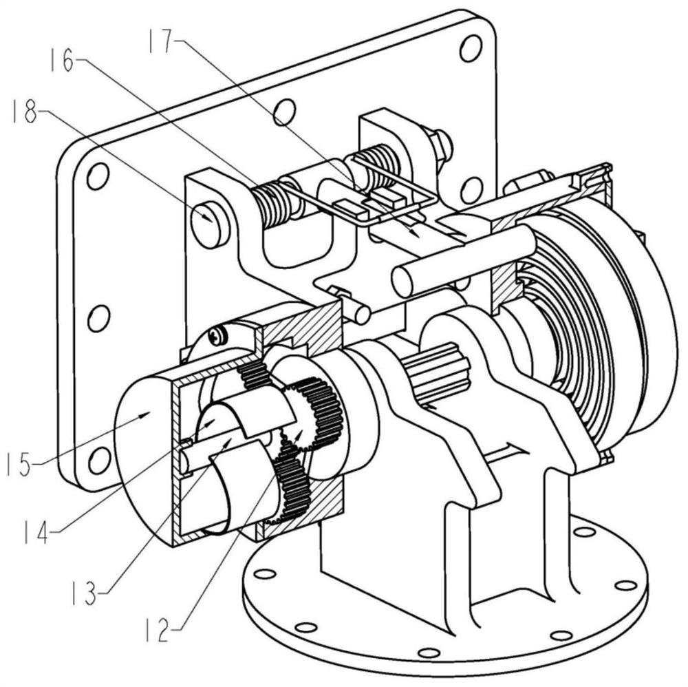
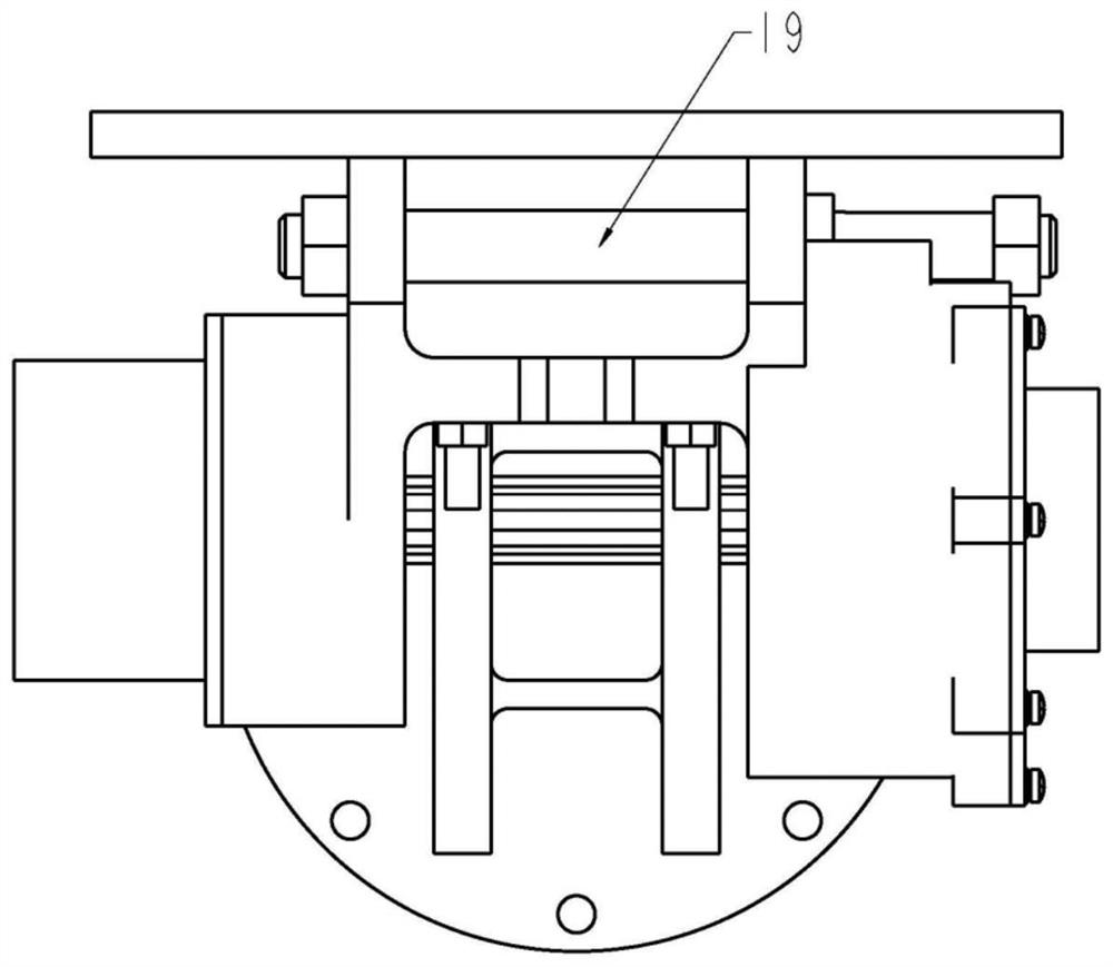
[0031] The present invention will be further elaborated below by describing a preferred specific embodiment in detail in conjunction with the accompanying drawings.

[0032] see Figure 1-5 , the present invention provides a technical solution: a low-impact hinge unfolding mechanism, including a first hinge 1, a central shaft 2, a second hinge 3, a power spring 4, a resistance spring 5, a flexible abrasive plate 14 and a friction box 15, Wherein the first hinge 1 is connected with the central shaft 2 through a bearing, and the central shaft 2 is connected with the second hinge 3 through a spline fit, and one end of the central shaft 2 has a notch and a screw thread, and the power The central mounting pieces of the spring 4 and the resistance spring 5 are all embedded in the gap of the central shaft 2, and the internal thread of the first nut 6 is a pipe thread. By tightening the first nut 6, the center shaft 2 The notch is closed inwardly, specifically, one end of the central...


PUM


Abstract

The invention discloses a low-impact hinge unfolding mechanism. The low-impact hinge unfolding mechanism comprises a first hinge, a center shaft, a second hinge, a power spring, a resistance spring, aflexible grinding piece and a friction box. The first hinge is connected with the center shaft through a bearing. The second hinge is arranged on the center shaft through a spline. The power spring and the resistance spring are arranged at one end of the center shaft, and the other end of the center shaft is connected with the flexible grinding piece through a planetary gear train. The flexible grinding piece makes contact with the inner wall of the friction box. According to the low-impact hinge unfolding mechanism, two volute spiral springs are adopted for providing power and resistance correspondingly, and the resultant force is kept stable in the whole unfolding action process by adjusting parameters of the two springs; the unfolding angular speed of a planetary gear train amplifyingmechanism is adopted, and the flexible grinding piece is driven to conduct friction energy dissipation along the inner wall of the friction box; and when the unfolding angular speed is too large, thefriction resistance of the flexible grinding piece is increased under the action of centrifugal force, more resistance torque is provided for the mechanism, and accordingly, the unfolding speed is reduced, and impact is reduced.

Description

Technical field [0001] The invention relates to the technical field of spacecraft passive deployment mechanisms, and in particular to a low-impact hinge deployment mechanism. Background technique [0002] The antenna on the satellite needs to be unfolded from the folded state to the working state after the satellite is in orbit. Usually such unfolding tasks are one-time. The hinge unfolding mechanism has the advantages of low cost and high reliability, so it is widely used in satellite antenna unfolding tasks. middle. However, as the size of satellite antennas increases and the mass of the antennas becomes lighter, the disadvantage of the traditional hinge deployment mechanism is that the impact is too large at the end of the deployment action. Due to the lack of resistance in space, the vibration of the antenna caused by a large impact is difficult to dissipate quickly, which can easily cause instability in the performance of the antenna. Excessive instantaneous impact may...

Claims


Application Information

Patent Timeline
Patent Type & Authority Applications(China)
IPC IPC(8): F16C11/04F16C11/10F16F7/04F16D59/02H01Q1/08
CPCF16C11/04F16C11/10F16F7/023F16D59/02H01Q1/08F16F2230/0005F16F2238/026F16C2326/47F16C2380/00
Inventor 李前魏颖高林星张衡丰超
Owner SHANGHAI RADIO EQUIP RES INST
Why Eureka
Try Eureka