
Spindle structure of drilling and milling center machine tool

A technology of machine tool spindles and drilling and milling centers, applied in the field of machine tools, can solve problems such as weak drilling capabilities and low-precision machining centers, and achieve the effect of solving high-torque cutting problems and increasing radial rigidity

Inactive Publication Date: 2021-03-09
NINGXIA YINCHUAN DAHE CNC MACHINE
View PDF0 Cites 0 Cited by
  • Summary
  • Abstract
  • Description
  • Claims
  • Application Information

AI Technical Summary

Problems solved by technology

Therefore, the drilling and milling center where the spindle is installed is actually a low-precision machining center, which is suitable for milling functions and has weak drilling capabilities.

Method used


Image

  • Spindle structure of drilling and milling center machine tool
  • Spindle structure of drilling and milling center machine tool
  • Spindle structure of drilling and milling center machine tool

Examples


Embodiment 1

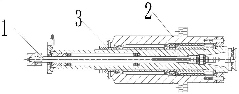
[0028] like figure 1 As shown, a main shaft structure of a drilling and milling center machine tool includes a main shaft 1, a main shaft sleeve 2 and a matching assembly 3, the main shaft 1 is arranged inside the main shaft sleeve 2, and the matching assembly 3 is arranged between the main shaft 1 and the main shaft sleeve 2.

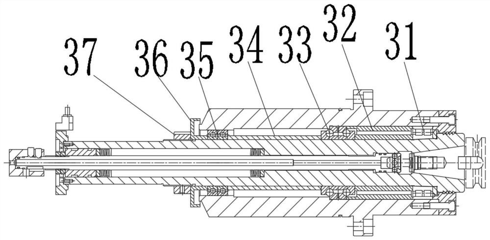
[0029] like figure 2 As shown, the matching assembly 3 includes a double-row radial cylindrical roller bearing 31, a two-way thrust angular contact ball bearing 32, a spacer set 33, a third spacer 34, a deep groove ball bearing 35, an oil deflector ring 36 and a second lock Tight nut 37, double-row radial cylindrical roller bearing 31 is nested in the tail end of main shaft 1, bidirectional thrust angular contact ball bearing 32 is nested in the middle of main shaft 1, spacer set 33 is arranged on the outer periphery of main shaft 1, spacer set 33 two Two-row radial cylindrical roller bearings 31 and two-way thrust angular contact ball bearings 32 ar...


PUM


Abstract

The invention provides a spindle structure of a drilling and milling center machine tool. The spindle structure comprises a spindle, a spindle sleeve and a matching assembly, wherein the spindle is arranged in the spindle sleeve; the matching assembly is arranged between the spindle and the spindle sleeve; the matching assembly comprises a double-row centripetal cylindrical roller bearing, a bidirectional thrust angular contact ball bearing and a spacer bush set; the double-row centripetal cylindrical roller bearing is nested at the tail end of the spindle; the bidirectional thrust angular contact ball bearing is nested in the middle of the spindle; the spacer bush set is arranged on the periphery of the spindle; and the two ends of the spacer bush set are closely attached to the double-row centripetal cylindrical roller bearing and the bidirectional thrust angular contact ball bearing correspondingly. According to the spindle structure, the method that the double-row centripetal cylindrical roller bearing and the bidirectional thrust angular contact ball bearing are used in cooperation is adopted, and the problems about axial resistance and radial stress are solved.

Description

technical field [0001] The invention relates to the field of machine tools, in particular to a spindle of a drilling and milling center machine tool. Background technique [0002] With the adjustment of industrial technology, the market has higher requirements for the performance of machine tools (such as turning and milling compound centers). Drilling and milling centers currently on the market mainly use two structural forms: the spindle of the drilling machine or the spindle of the machining center. Drilling machine spindles have low milling efficiency and poor milling flatness, which cannot meet market requirements; machining center spindles have high milling accuracy, but the spindle’s resistance to force is poor. The precision of the cutting function spindle decreases, which directly affects the precision of the machine tool. This invention solves the problem of the radial force on the spindle during milling, and has the ability to resist the force of the spindle dur...

Claims


Application Information

Patent Timeline
IPC IPC(8): B23B19/02
CPCB23Q1/70
Inventor 刘波
Owner NINGXIA YINCHUAN DAHE CNC MACHINE
Features
  • Generate Ideas
  • Intellectual Property
  • Life Sciences
  • Materials
  • Tech Scout
  • Unparalleled Data Quality
  • Higher Quality Content
  • 60% Fewer Hallucinations
Learn More