Waste liquid treatment device for rare earth production
A waste liquid treatment, waste liquid technology, applied in the direction of metallurgical wastewater treatment, filtration treatment, special treatment goals, etc., can solve the problems of incomplete filtration, easy quality of discharged waste water, etc.
- Summary
- Abstract
- Description
- Claims
- Application Information
AI Technical Summary
Problems solved by technology
Method used
Image
Examples
Embodiment 1
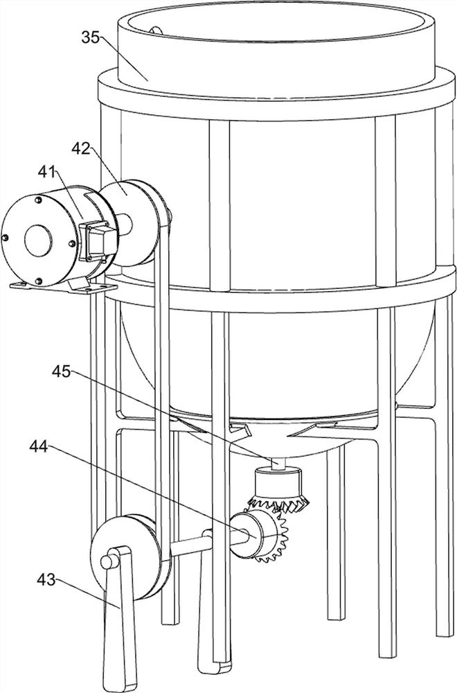
[0054] A waste liquid treatment device for rare earth production, such as Figure 1 to Figure 8 As shown, it includes a base 1, a mounting seat 2, a waste liquid flow mechanism 3, and a stirring and filtering mechanism 4. A mounting seat 2 is provided on the left front side of the top of the base 1, and a waste liquid flow mechanism 3 is provided on the rear side of the top of the base 1. The waste liquid flow direction A stirring and filtering mechanism 4 is connected to the mechanism 3 .
[0055]The waste liquid flow mechanism 3 includes a support seat 31, a waste liquid placement chamber 32, a water pump 33, a waste liquid outflow pipe 34, a waste liquid filter chamber 35, a filtered waste liquid flow pipe 36, a sedimentation tank 37, a water outlet switch 38 and clean water The outflow pipeline 39, the top of the base 1 is provided with three support seats 31, the support seat 31 is provided with a waste liquid placement chamber 32, a waste liquid filtration chamber 35 and...
Embodiment 2
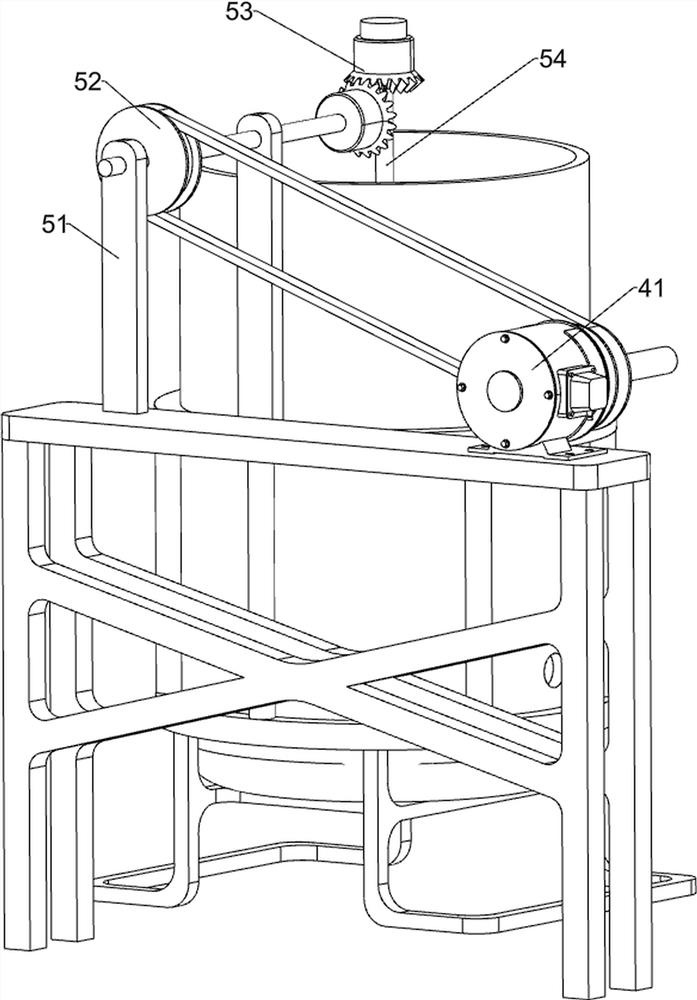
[0059] On the basis of Example 1, such as Figure 4 , Figure 5 , Figure 7 and Figure 9 As shown, it also includes an anti-waste liquid large particle impurity precipitation mechanism 5, and the waste liquid large particle impurity precipitation prevention mechanism 5 includes a mounting frame 51, a second pulley assembly 52, a second bevel gear set 53, a second rotating shaft 54, a filter Net 55 and anti-sedimentation stirring blade 56, mounting frame 51 is provided on the left side of the top of the mounting base 2, and a transmission rod is installed on the top of the mounting frame 51, and a second pulley assembly 52 is connected between the transmission rod and the output shaft of the servo motor 41 , the upper part of the waste liquid placement cavity 32 inner wall is provided with a filter screen 55, the filter screen 55 is rotatably provided with a second rotating shaft 54, and the bottom of the second rotating shaft 54 is provided with two anti-sedimentation sti...
Embodiment 3
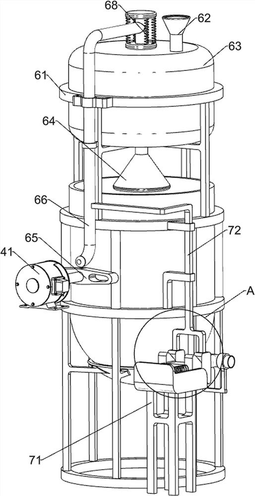
[0064] On the basis of Example 2, such as Figure 5 , Image 6 , Figure 10 , Figure 11 and Figure 12 As shown, the waste liquid automatic outflow mechanism 7 after filtration is also included, and the waste liquid automatic outflow mechanism 7 after filtration includes a movable guide rail frame 71, a connecting frame 72, a first wedge block 73, a second wedge block 74, a return spring 75, Connecting post 76 and blocking post 77, base 1 top right front side is provided with movable guide rail frame 71, is provided with return spring 75 symmetrically on movable guide rail frame 71, is connected with second wedge-shaped block 74 between the return spring 75 rear ends, middle side supports The right side of the seat 31 is slidably connected with a connecting frame 72, the left end of the connecting frame 72 is connected with the blocking block 66, and the bottom of the connecting frame 72 is connected with two first wedge-shaped blocks 73, and the first wedge-shaped block 7...
PUM
 Abstract
Description
Claims
Application Information
 - R&D
- Intellectual Property
- Life Sciences
- Materials
- Tech Scout
- Unparalleled Data Quality
- Higher Quality Content
- 60% Fewer Hallucinations
Browse by: Latest US Patents, China's latest patents, Technical Efficacy Thesaurus, Application Domain, Technology Topic, Popular Technical Reports.
© 2025 PatSnap. All rights reserved.Legal|Privacy policy|Modern Slavery Act Transparency Statement|Sitemap|About US| Contact US: help@patsnap.com


