Scroll compressor

A scroll compressor and moving scroll technology, applied in the field of compressors, can solve problems such as over-compression and increased compression power consumption

Pending Publication Date: 2021-03-09
ZHUHAI GREE REFRIGERATION TECH CENT OF ENERGY SAVING & ENVIRONMENTAL PROTECTION
View PDF0 Cites 1 Cited by
  • Summary
  • Abstract
  • Description
  • Claims
  • Application Information

AI Technical Summary

Problems solved by technology

The phase angle difference between the movable scroll and the fixed scroll is 180 degrees. The movable scroll moves under the drive of the crankshaft and meshes with the fixed scroll to form a series of crescent-shaped airtight chambers that are isolated from each other and whose volume changes continuously. When the compression chamber After the refrigerant inside is compressed to the position of the disengagement point of the profile line, the compression chamber communicates with the discharge port of the fixed scroll and starts to exhaust. Because it still needs to rotate at a certain angle from the disengagement of the scroll profile line to the large opening exhaust, this There will be over-compression problems in the process, which will increase the compression power consumption

Method used


Image

  • Scroll compressor
  • Scroll compressor
  • Scroll compressor

Examples


Embodiment Construction

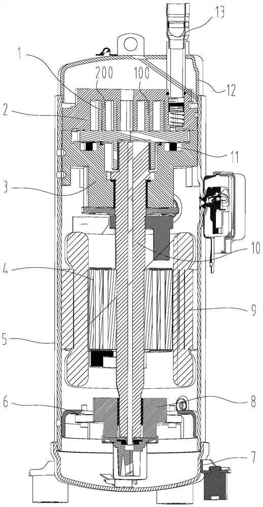
[0028] see in conjunction Figure 1 to Figure 7 As shown, according to the embodiment of the present application, the scroll compressor includes a movable scroll 1, a fixed scroll 2, an upper bracket 3, a rotor 4, a casing 5, a lower support ring 6, a lower cover 7, a lower bracket 8, a motor 9. Crankshaft 10, Oldham slip ring 11, upper cover 12, etc. The motor 9 is fixed on the housing 5 through a shrink fit, and the upper bracket 3 is fixed on the housing 5 through eight-point welding. The phase angle difference between the movable scroll 1 and the fixed scroll 2 is 180 degrees, and it is installed on the upper bracket 3. The movable scroll 1 moves under the drive of the crankshaft 10, and meshes with the fixed scroll 2 to form a series of mutually isolated and continuously changing volumes. The crescent-shaped airtight cavity, the fixed scroll 2 is fixed on the upper bracket 3 by screw fasteners. The crankshaft assembly is supported by a lower bracket 8, and the lower bra...


PUM


Abstract

The invention provides a scroll compressor. The scroll compressor comprises a movable scroll plate and a static scroll plate; the movable scroll plate comprises an inner side molded line, an outer side molded line and a tooth head molded line; the static scroll plate comprises an inner side molded line, an outer side molded line and a tooth head molded line; the movable scroll plate inner side molded line comprises a first arc section and a first involute section; the static scroll plate outer side molded line comprises a fourth arc section and a fourth involute section; the first arc sectionis located on the side, away from the first tooth head molded line, of a first inner disengagement point, and the fourth arc section is located on the side, away from the second tooth head molded line, of a second outer disengagement point; and / or the movable scroll plate outer side molded line comprises a second arc section and a second involute section; the static scroll plate inner side moldedline comprises a third arc section and a third involute section; and the second arc section is located on the side, away from the first tooth head molded line, of the first outer disengagement point,and the third arc section is located on the side, away from the second tooth head molded line, of the second inner disengagement point. According to the scroll compressor provided by the invention, rapid exhaust can be achieved, exhaust overcompression is reduced, and the efficiency of the compressor is improved.

Description

technical field [0001] The present application relates to the technical field of compressors, in particular to a scroll compressor. Background technique [0002] The scroll compressor has the advantages of simple structure, small size, light weight, low noise, high mechanical efficiency and stable operation. A scroll compressor is a fluid machine that achieves gas compression by means of volume changes. The dynamic and static scrolls are the main parts of the pump body. The most commonly used profiles of the dynamic and static scrolls are circular involutes and their correction curves. The phase angle difference between the movable scroll and the fixed scroll is 180 degrees. The movable scroll moves under the drive of the crankshaft and meshes with the fixed scroll to form a series of crescent-shaped airtight chambers that are isolated from each other and whose volume changes continuously. When the compression chamber After the refrigerant inside is compressed to the positi...

Claims


Application Information

Patent Timeline
IPC IPC(8): F04C18/02F04C29/00
CPCF04C18/0215F04C18/0269F04C2240/10F04C2240/20
Inventor 胡余生徐嘉李海港单彩侠刘双来律刚
Owner ZHUHAI GREE REFRIGERATION TECH CENT OF ENERGY SAVING & ENVIRONMENTAL PROTECTION
Why Eureka
Try Eureka