Power system operation state comprehensive monitoring system

A technology for operating status and comprehensive monitoring, applied in system integration technology, information technology support systems, current collectors, etc., can solve problems such as increased labor costs, difficulty for staff to carry targeted equipment and tools, and increased difficulty in maintenance. Achieve the effect of reducing maintenance difficulty, extending battery life and improving maintenance efficiency

Pending Publication Date: 2021-03-09
CHINA SOUTHERN POWER GRID COMPANY
View PDF6 Cites 2 Cited by
  • Summary
  • Abstract
  • Description
  • Claims
  • Application Information

AI Technical Summary

Problems solved by technology

4. System collapse: the inequality and equality constraints are not satisfied at the same time, and the system will be decomposed into several independent small systems
[0003] During the use of the existing power state monitoring system, because it only monitors through the circuit, there will be a problem that the monitoring is not in place when encountering an emergency, so that the background monitoring personnel cannot accurately judge the fault information, and can only check it on the spot. Labor cost, and because the on-site situation cannot be controlled, it is difficult for the staff to carry targeted equipment and tools, making maintenance more difficult. In addition, the batteries of the existing power monitoring system are generally charged through the main grid, and in some remote In regions, after the equipment is powered off, the duration of the battery is limited, which often causes monitoring interruptions

Method used


Image

  • Power system operation state comprehensive monitoring system

Examples


Embodiment

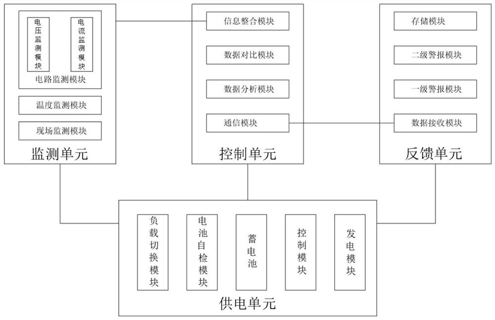
[0025] refer to figure 1 , a comprehensive monitoring system for power system operation status proposed by the present invention, comprising:

[0026] A monitoring unit, the monitoring unit includes a circuit monitoring module, a temperature monitoring module and an on-site monitoring module, wherein the circuit monitoring module includes a voltage monitoring module and a current monitoring module, wherein the on-site monitoring module includes an image monitoring system, a sound monitoring System and smoke detection system, specifically, the image monitoring system and sound monitoring system can use real-time video monitoring technology, in which the image monitoring system has lightning protection and night shooting mode to avoid lightning damage, and can use infrared with lightning protection function The smart camera can shoot when the light is insufficient, and upload the captured signal to the communication device through the monitoring host in real time, while the smok...


PUM


Abstract

The invention discloses an electric power system operation state comprehensive monitoring system, and the system comprises a monitoring unit comprising a circuit monitoring module, a temperature monitoring module and an on-site monitoring module; a control unit which comprises an information integration module, a data comparison module, a data analysis module and a communication module; the feedback unit comprises a data receiving module, a primary alarm module, a secondary alarm module and a storage module; and a power supply unit which comprises a load switching module, a battery self-checking module, a storage battery, a control module and a power generation module, wherein the monitoring unit is used for monitoring a power machine room site and monitoring a circuit, a temperature and asite environment, and the control unit is used for integrating various kinds of information to make a judgment and transmitting a signal to the feedback unit. By arranging multiple detection modules,background maintenance personnel are helped to remotely control more and more accurate fault information, maintenance personnel are helped to reduce the maintenance difficulty, and the maintenance efficiency is improved.

Description

technical field [0001] The invention relates to the technical field of power system monitoring, in particular to a comprehensive monitoring system for power system operation status. Background technique [0002] According to different operating conditions, the operating state of the power system can be divided into normal state, abnormal state and fault state. The basis for running a schedule. 2. Alert state: Equality and inequality constraints are met, but the inequality constraints are close to the upper and lower limits, and safety scheduling is the main focus. 3. Emergency state: the inequality constraint is broken, the equality constraint can still be satisfied, and the system can still run synchronously. 4. System collapse: If the inequality and equality constraints are not satisfied at the same time, the system will be decomposed into several independent small systems. 5. Restoration state: Transition from several small systems after the crash to the running state ...

Claims


Application Information

Patent Timeline
Patent Type & Authority Applications(China)
IPC IPC(8): H02J13/00H02J7/35
CPCH02J13/00002H02J7/35Y04S10/123Y02E40/70
Inventor 黄方能周剑梅勇
Owner CHINA SOUTHERN POWER GRID COMPANY
Why Eureka
Try Eureka