
Method for controlling flow of simulation fire source

A technology for simulating fire source and flow control, which is applied in combustion methods, combustion control, and fuel supply regulation. The effect of reducing the impact and facilitating the remote control operation

Active Publication Date: 2012-05-23
广州市建筑材料工业研究所有限公司
View PDF2 Cites 0 Cited by
  • Summary
  • Abstract
  • Description
  • Claims
  • Application Information

AI Technical Summary

Problems solved by technology

The disadvantages of this utility model are: (1) the system needs to use fuel oil and gas to burn together, forming a large-scale on-site simulation state, which can only simulate a large-scale fire scene; (2) the system requires the use of a special cylindrical spray gun, It is impossible to use many different types of burners to simulate the fire source, and it cannot be as close to the real combustion situation as possible
This utility model can control the ignition time of the burner and the gas flow, but because the gas flow adjustment is manually realized through the needle valve of the rotameter, this adjustment method has the following disadvantages: (1) The accuracy of the rotameter is generally not high , resulting in difficult measurement of the rotameter scale and poor accuracy; (2) The adjustment of the flow rate of the rotameter must be adjusted manually on site, and remote automatic control is not possible, let alone program control; (3) The reading of the rotameter It is greatly affected by the pressure value before and after the pipeline, flow velocity, pipeline conditions and other external influences

Method used


Image

  • Method for controlling flow of simulation fire source
  • Method for controlling flow of simulation fire source
  • Method for controlling flow of simulation fire source

Examples


Embodiment 1

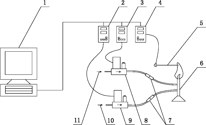
[0031] Such as figure 1 As shown, a flow control device simulating a fire source includes a computer 1, a gas intelligent control instrument 2, a gas-supporting intelligent control instrument 3, a temperature acquisition intelligent instrument 4, a thermocouple 5, a burner 6, a gas source 10, a gas Mass flowmeter 9, gas-supporting gas source 11, gas-supporting mass flowmeter 8, the gas gas source 10 is connected to the inlet of the gas mass flowmeter 9, and the outlet of the gas mass flowmeter 9 is connected to the burner 6 through the quick connector 7 , the gas-supporting gas source 11 is connected to the inlet of the gas-supporting mass flowmeter 8, and the outlet of the combustion-supporting gas mass flowmeter 8 is connected to the burner 6 through the quick joint 7; the gas mass flowmeter 9, the gas intelligent control instrument 2, the computer 1 are connected in sequence, the gas-supporting mass flowmeter 8, the gas-supporting intelligent control instrument 3, and the c...

Embodiment 2

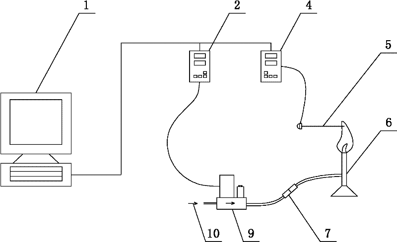
[0046] Present embodiment except following feature other structures are with embodiment 1: as image 3 As shown, the gas-supporting mass flowmeter 8, the gas-supporting intelligent control instrument 3, and the gas-supporting gas source 11 in the device of Example 1 are removed, and the combustion-supporting gas is not used when simulating the combustion of the fire source.

[0047] The gas intelligent control instrument 2 , the gas-supporting intelligent control instrument 3 , and the temperature acquisition intelligent instrument 4 communicate directly with the computer 1 through the USB interface.

[0048] The type of the gas source 10 is methane.

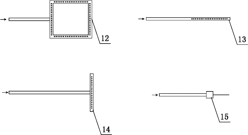
[0049] The burner is a needle flame burner with a structure such as figure 2 15 in.

Embodiment 3

[0051] The structure of this embodiment is the same as that of Embodiment 1 except for the following features: the input and output control signals of the gas mass flowmeter 9 and the assisted gas mass flowmeter 8 are voltage signals of 0-5V.

[0052] The gas source 10 is propane.

[0053] The type of the combustion-supporting gas source 11 is oxygen.

[0054] The burner is a linear burner with a structure such as figure 2 13 in.

[0055] In the step (3) of the flow control method for simulating fire sources, after the temperature acquisition intelligent instrument transmits the temperature data to the computer, the computer judges whether the temperature data is in the set temperature range, if the temperature data is higher than the set temperature range Temperature range, then the computer reduces the original set gas and assisted gas flow, and vice versa, the gas and assisted gas flow is reduced according to 0.05-0.2L / min, until the temperature data obtained by feedback...


PUM


Abstract

The invention discloses a method and device for controlling the flow of a simulation fire source. The method provided by the invention comprises the following steps: a system is initialized; an intelligent control meter transmits the gas flow and the auxiliary gas flow preset by a computer to a corresponding mass flow meter; the output gas and auxiliary gas flow values achieve the target flow by utilizing the mass flow meter; in the combustion course, a thermocouple collects feedback signals to the computer, thereby adjusting the set flow value; and when the combustion finally ends, the flow signal of the computer is 0, the mass flow meter is controlled to be closed, and the simulation ignition ends. The device provided by the invention comprises the computer, the gas intelligent control meter, the auxiliary gas intelligent control meter, a temperature collection intelligent meter, a thermocouple, a combustor, a gas source, a gas mass flow meter, an auxiliary gas source and an auxiliary gas mass flow meter. The invention can remotely and accurately control the fluid at different times to reach different flows in real time by adopting the mass flow meter and combining the computer to control the flow of the combustor.

Description

technical field [0001] The invention belongs to the field of simulated fire source design, in particular to a flow control method for simulated fire source. Background technique [0002] For plastic products such as building decoration materials, indoor furniture, decorations, electrical appliances, etc., in order to test their dangerous conditions in the event of fire, it is necessary to test their combustion performance. A method commonly used at present is to simulate a possible fire. The fire source ignites the tested sample to observe whether it spreads, expands, etc. This method requires that the simulated fire source not only have a certain flame size, but also require the shape of the flame to be consistent with the actual fire that may occur. For example, for the combustion performance test of mattresses, when it is necessary to study matches to ignite mattresses, a small flame is required, and the size and shape of the heat released should be similar to the flame w...

Claims


Application Information

Patent Timeline
Patent Type & Authority Patents(China)
IPC IPC(8): F23N1/02G01N31/12
Inventor 刘建勇杨展林玩君赵侠易爱华邬玉龙吴欣田素琴余稳松
Owner 广州市建筑材料工业研究所有限公司
Learn More