Chemical plant flue gas desulfurization, denitration and dust removal equipment
A technology for desulfurization, denitrification, and dust removal equipment, which is applied in chemical instruments and methods, dispersed particle separation, and dispersed particle filtration.
- Summary
- Abstract
- Description
- Claims
- Application Information
AI Technical Summary
Problems solved by technology
Method used
Image
Examples
Embodiment 1
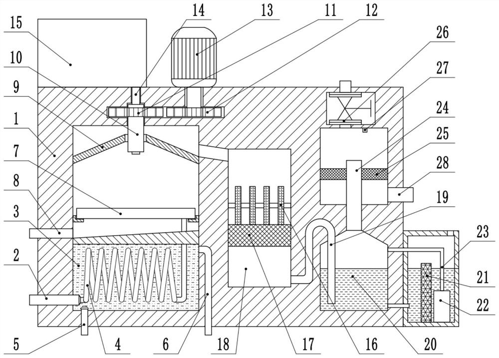
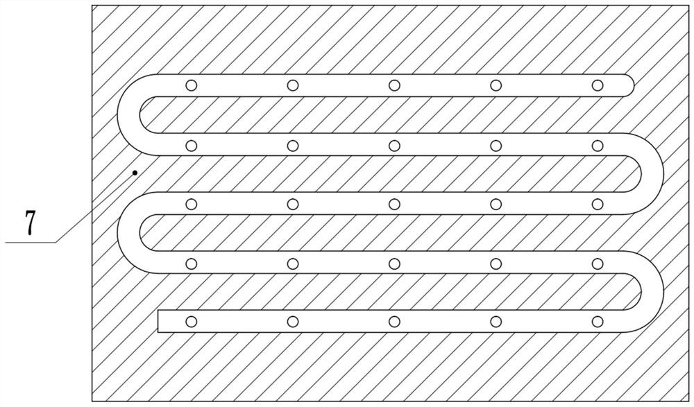
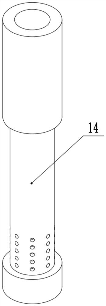
[0023] see Figure 1-4 , a chemical plant flue gas desulfurization, denitrification and dust removal equipment, including a box body 1, the inside of the box body 1 is respectively provided with a cooling device, a drying device, and a denitrification device from left to right, and a desulfurization device is provided above the cooling device. A gas outlet device is arranged above the denitrification device, and a flue gas pipeline 4 is arranged in the cooling device. A first conduit 19 is provided at the end, and the first conduit 19 communicates with the pin-out device, and a second conduit 24 is provided at the top of the pin-out device, and the second conduit 24 communicates with the air outlet device.
[0024] The cooling device includes a cooling liquid 3, the inside of the box 1 is provided with a cooling liquid 3 tank, the cooling liquid 3 is arranged in the cooling liquid 3 groove, and the flue gas pipe 4 is arranged in the cooling liquid 3 and is snake-shaped. The s...
Embodiment 2
[0030] see Figure 1-4 , the other content of this embodiment is the same as that of Embodiment 1, the difference is that: the drying device includes an activated carbon plate 17, a drying chamber 18 is provided inside the box body 1, and the activated carbon plate 17 is connected to the side end of the drying chamber 18. Fixedly connected, the top of the activated carbon plate 17 is fixedly connected to a plurality of heating and drying plates 16, and the side end of the first guide rod communicates with the side end of the drying chamber 18 below the activated carbon plate 17.
[0031] During the implementation of the present invention, flue gas is rushed into the device through the air intake pipe 2, and after being cooled by the cooling mechanism, it is passed into the desulfurization chamber, and the cooling liquid 3 in the cooling chamber is cooled by the cooling liquid inlet 5 and the cooling liquid outlet 6. Replacement, maintain the temperature of the cooling liquid 3...
PUM
 Abstract
Description
Claims
Application Information
 - R&D
- Intellectual Property
- Life Sciences
- Materials
- Tech Scout
- Unparalleled Data Quality
- Higher Quality Content
- 60% Fewer Hallucinations
Browse by: Latest US Patents, China's latest patents, Technical Efficacy Thesaurus, Application Domain, Technology Topic, Popular Technical Reports.
© 2025 PatSnap. All rights reserved.Legal|Privacy policy|Modern Slavery Act Transparency Statement|Sitemap|About US| Contact US: help@patsnap.com


