Photocatalyst air purification device

An air purification device and photocatalyst technology, applied in chemical instruments and methods, dispersed particle separation, separation methods, etc., can solve the problems of insufficient contact area, increased cost, short contact time, etc., and achieve the effect of increasing the contact area

Active Publication Date: 2021-03-12
FUSHUN MATERIAL TECH CO LTD
View PDF11 Cites 2 Cited by
  • Summary
  • Abstract
  • Description
  • Claims
  • Application Information

AI Technical Summary

Problems solved by technology

[0003] For example, Chinese Patent Announcement No. CN111359600A "Ball No. of Wastewater and Gas Pollutants Treatment Loaded with Composite Modified Nano-TiO2", the patent has a porous sphere, surface and pores Medium-coating composite modified nano-TiO2 and plant-extracted photosensitizer or strong oxidant, but the photocatalyst needs high-energy light to continuously stimulate the reaction. Therefore, the method of using natural light in this patent cannot effectively stimulate the photocatalyst reaction.
[0004] Another example is Taiwan Patent Announcement No. M359368 "New Structure of Photooxidation Tank". Tube) is filled with TiO2 nanometer photocatalyst glass balls, and a plurality of ultraviolet lamps are arranged outside the first tube; this patent is for purifying organic substances in water, so the ultraviolet lamps cannot be installed in the first tube, and at the same time, the ultraviolet lamps The emitted ultraviolet rays, after passing through the first tube body, will produce the first reflection and refraction, and then pass through the water to be purified and TiO2 nano photocatalyst glass balls, then the ultraviolet rays generated by the left ultraviolet lamp tube will reach On the right side of the first tube body, the ultraviolet rays have been refracted many times, which has caused quite serious attenuation and loss. Therefore, in order to allow the TiO2 nano photocatalyst glass balls to irradiate ultraviolet rays evenly, it is more necessary to Setting multiple ultraviolet lamps around the first tube body not only greatly increases the cost, but also leads to a large amount of power consumption
[0005] In addition to the above-mentioned patents, although photocatalysts are used as a means to further purify the air in the current air cleaning devices, there are gaps between the air and the photocatalyst layer. Problems such as short contact time and insufficient contact area lead to extremely poor efficiency of photocatalyst purification

Method used


Image

  • Photocatalyst air purification device
  • Photocatalyst air purification device
  • Photocatalyst air purification device

Examples


Embodiment Construction

[0043] The following will clearly and completely describe the technical solutions in the embodiments of the present invention with reference to the accompanying drawings in the embodiments of the present invention. Obviously, the described embodiments are only some, not all, embodiments of the present invention. Based on the embodiments of the present invention, all other embodiments obtained by persons of ordinary skill in the art without making creative efforts fall within the protection scope of the present invention.

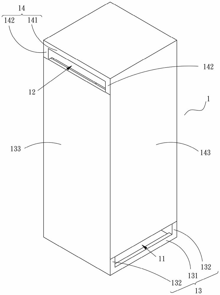
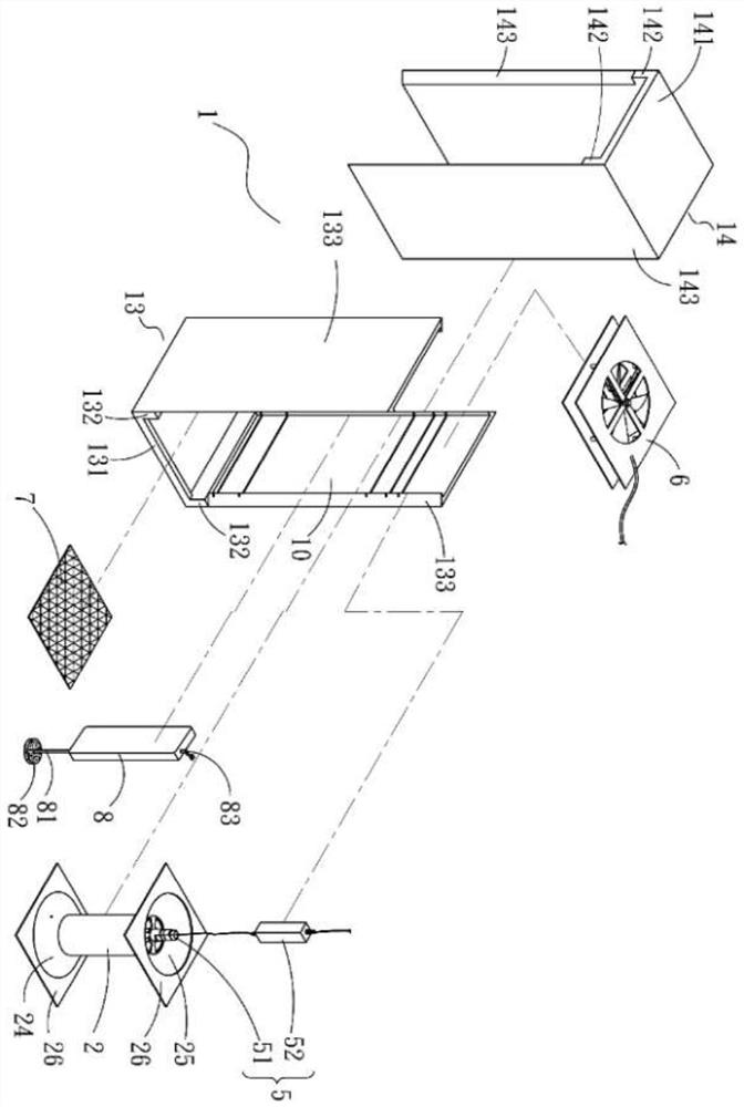
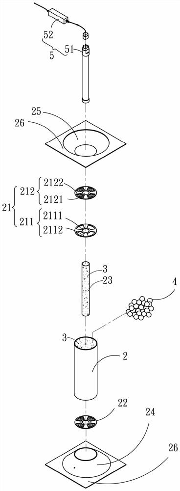
[0044] see Figure 1 to Figure 3 As shown, it can be seen that the structure of the present invention mainly includes: a box body 1, a first pipe body 2, a plurality of inorganic substances 4, an ultraviolet module 5, and a fan 6, wherein:

[0045] One end of the box body 1 has an air inlet 11, the other end has an exhaust port 12, and the inside has an accommodating space 10 communicating with the outside. It should be noted that the inside of the box body ...


PUM


Abstract

The invention discloses a photocatalyst air purification device which is provided with a box body; a first pipe body, an ultraviolet module and a fan are arranged in the box body; a second pipe body is arranged in the first pipe body and filled with a plurality of light-transmitting inorganic substances, and photocatalyst layers are arranged on the surfaces of the inorganic substances, the inner wall of the first pipe body and the outer wall of the second pipe body. An ultraviolet lamp tube of the ultraviolet module is arranged in the second tube body in a sleeving manner; therefore, the ultraviolet lamp tube generates ultraviolet rays, the ultraviolet rays are projected to the inorganic matter through the second tube body and then are greatly refracted and reflected through the inorganicmatter, and the contact area of the ultraviolet rays and the photocatalyst layer can be increased; after the fan is actuated, air outside the box body enters the first pipe body through the air inlet,and the structure that the air makes contact with the photocatalyst layer, so that organic matter in the air is oxidized and degraded or reduced is achieved.

Description

technical field [0001] The invention relates to an air purification device, in particular to a photocatalyst air purification device capable of increasing the coverage of ultraviolet-excited photocatalyst coating, increasing the contact area between gas and photocatalyst, and further improving the oxidation degradation of photocatalyst and reducing organic matter in gas. Background technique [0002] There are quite a lot of technical means to purify water or air. In recent years, a very popular technology is the use of photocatalyst. Photocatalyst is a kind of "catalyst that uses light energy to carry out catalytic reactions". Before use, it will be coated or sprayed on the surface of the object to form a thin film, and then through the activation of light energy (such as ultraviolet rays), it will oxidize and degrade or reduce the foreign substances attached to the surface of the object, so as to remove The purpose of decontamination, sterilization, antibacterial or surfac...

Claims


Application Information

Patent Timeline
IPC IPC(8): B01D53/86B01D53/44
CPCB01D53/8687B01D2255/802
Inventor 陈源成
Owner FUSHUN MATERIAL TECH CO LTD
Why Eureka
Try Eureka