Supercharge Your Innovation With Domain-Expert AI Agents!

Building steel bar cutting device

A cutting device and technology for construction, applied in the field of construction, can solve the problems of difficult to guarantee cutting quality and efficiency, and difficult to remove

Inactive Publication Date: 2021-03-12
钟玲
View PDF0 Cites 1 Cited by
  • Summary
  • Abstract
  • Description
  • Claims
  • Application Information

AI Technical Summary

Problems solved by technology

[0003] The existing steel bar cutting device is difficult to firmly clamp the steel bar during cutting, and it is not easy to remove after clamping, which makes it difficult to guarantee the cutting quality and efficiency

Method used


Image

  • Building steel bar cutting device
  • Building steel bar cutting device
  • Building steel bar cutting device

Examples


Embodiment 1

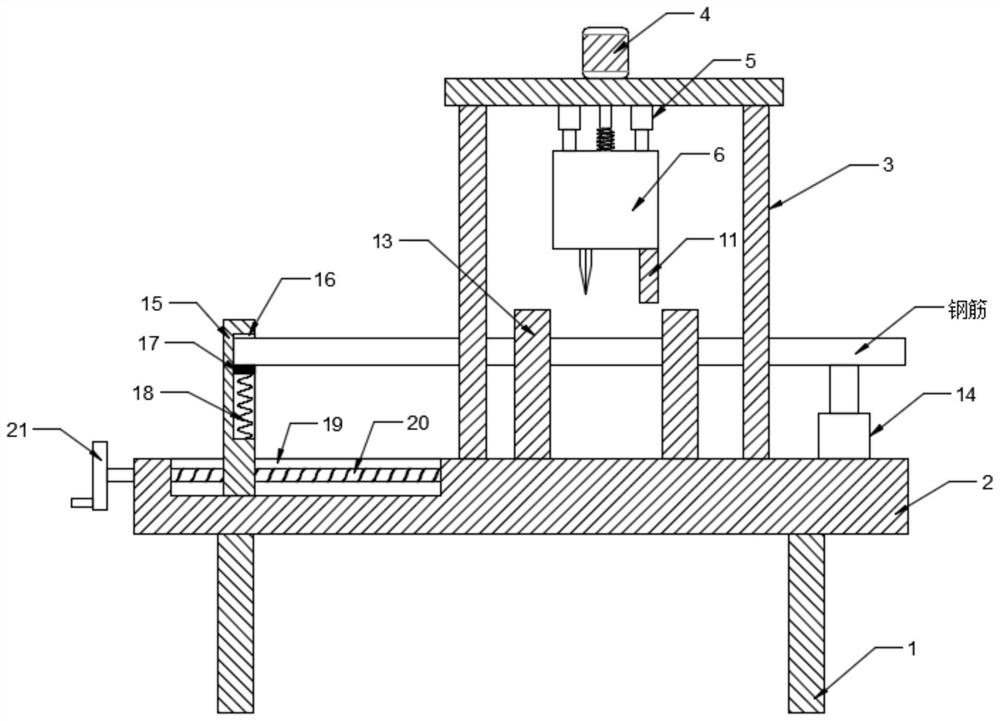
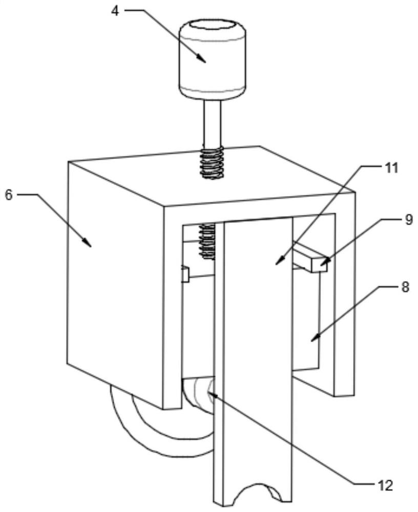
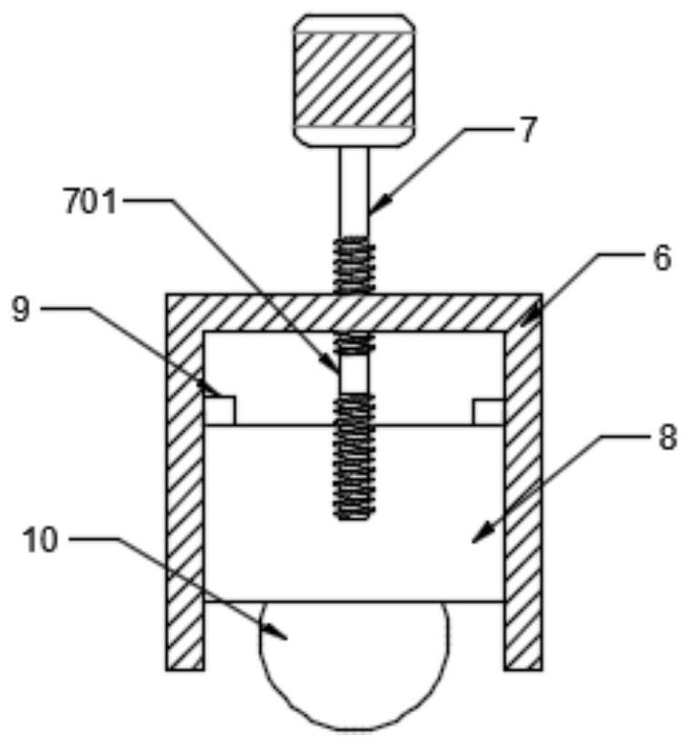
[0025] see Figure 1-5 , a steel bar cutting device for construction, comprising a column 1, a workbench 2 and a stand 3, the stand 3 is installed on the workbench 2, the workbench 2 is installed on the column 1, and the stand 3 is provided with a steel bar cutting Assemblies, the specific type of the steel bar cutting assembly is not limited. In this embodiment, preferably, the steel bar cutting assembly includes a drive motor 4, a telescopic rod 5, a lifting frame 6, a screw mandrel 7, a lifting block 8, a clip 9, a cutting Knife 10, pressing plate 11 and cutting motor 12, described driving motor 4 is fixedly installed on the stand 3 and the output end is driven and connected with screw mandrel 7, and the middle part of described screw mandrel 7 is provided with smooth section 701, and described lifting frame 6 passes through The telescopic rod 5 is installed on the stand 3 and is threadedly connected to the top of the smooth section 701. The lifting block 8 is slidably inst...

Embodiment 2

[0033] In order to improve the practicability, this embodiment is further improved on the basis of Embodiment 1. The improvement is that: the workbench 2 is provided with a cutting position adjustment assembly, and the specific type of the cutting position adjustment assembly is not limited. Among the examples, preferably, the cutting position adjustment assembly includes a sliding rod 15, a chute 19, a threaded rod 20 and a rotating disk 21, the chute 19 is provided on the workbench 2, and the threaded rod 20 is rotatably installed in the chute 19 and one end extends to The outside of the workbench 2 is fixedly connected with the turntable 21, the sliding rod 15 is slidably arranged in the chute 19 and is threadedly connected with the threaded rod 20, the surface of the workbench 2 outside the chute 19 is provided with a scale, and the sliding is adjusted through the turntable 21. The position of the bar 15 can determine the cutting position when one end of the steel bar touch...


PUM


Abstract

The invention discloses a building steel bar cutting device which comprises a stand column, a workbench and a vertical frame. The vertical frame is installed on the workbench; the workbench is installed on the stand column; a steel bar cutting assembly is arranged on the vertical frame and comprises a driving motor, a telescopic rod, a lifting frame, a lead screw, a lifting block, a clamping strip, a cutting knife, a pressing plate and a cutting motor; the driving motor is fixedly installed on the vertical frame; the output end of the driving motor is in driving connection with the lead screw;a smooth section is arranged in the middle of the lead screw; the lifting frame is installed on the vertical frame through a telescopic rod and is in threaded connection with the upper part of the smooth section; the lifting block is slidably installed in the lifting frame; the upper end of the lifting block is in threaded connection with the lower part of the smooth section; the clamping strip and the smooth section are located at the same height and fixedly installed on the inner wall of the lifting frame; the cutting motor is fixedly installed at the lower end of the lifting block; the output end of the cutting motor is fixedly connected with the cutting knife; the pressing plate is installed on the lifting frame; and the lower end of the pressing plate is located below the lifting frame. Through arranging the steel bar cutting assembly, the cutting quality is greatly improved.

Description

technical field [0001] The invention relates to the construction field, in particular to a steel bar cutting device for construction. Background technique [0002] Building steel bars refer to various steel bars, steel wires, etc. used in reinforced concrete. Steel bars are divided into: non-alloy steel bars, low-alloy steel bars, and alloy steel bars. Steel bars are divided into: hot-rolled bars, heat-treated bars, waste heat-treated bars, cold-rolled bars, and cold-drawn bars. According to the shape, the steel bar is divided into: smooth round steel bar and deformed steel bar. During the building construction process, the building steel bars are usually cut to meet the needs of building construction. [0003] The existing steel bar cutting device is difficult to firmly clamp the steel bar during cutting, and it is not easy to remove after clamping, which makes it difficult to guarantee the cutting quality and efficiency. Contents of the invention [0004] The object o...

Claims


Application Information

Patent Timeline
IPC IPC(8): B21F11/00
CPCB21F11/00
Inventor 钟玲
Owner 钟玲
Features
  • R&D
  • Intellectual Property
  • Life Sciences
  • Materials
  • Tech Scout
  • Unparalleled Data Quality
  • Higher Quality Content
  • 60% Fewer Hallucinations
Learn More