Positioning clamp for sewing machine head shell machining

A technology of machine head shell and positioning fixture, which is applied in the field of sewing machines, can solve the problems that the position of the splint mechanism cannot be adjusted, increase the difficulty of shell processing, etc., and achieve the effects of convenient clamping, clamping limit, and improving processing efficiency

Inactive Publication Date: 2021-03-12
WUJIANG ZHENYU SEWING EQUIP
View PDF9 Cites 1 Cited by
  • Summary
  • Abstract
  • Description
  • Claims
  • Application Information

AI Technical Summary

Problems solved by technology

[0004] The purpose of the present invention is to provide a positioning fixture for sewing machine head shell processing, including a base and a column, a column is arranged above the base, a mounting seat is fixedly installed in the middle of the column, and mounting seats are symmetrically provided on both sides of the mounting seat for clamping. The clamping component of the shell, the mounting base and the clamping component are fixedly connected, a position adjustment component for adjusting the height of the column is arranged between the column and the base, two horizontal bars are symmetrically arranged on both sides of the mounting base, and the horizontal bar is fixed A limit plate is installed to limit the position of the shell. The limit plate is made of rubber material to solve the problem that the existing device cannot adjust the position of the splint mechanism, thus increasing the processing difficulty of the shell.

Method used


Image

  • Positioning clamp for sewing machine head shell machining
  • Positioning clamp for sewing machine head shell machining
  • Positioning clamp for sewing machine head shell machining

Examples


Embodiment 1

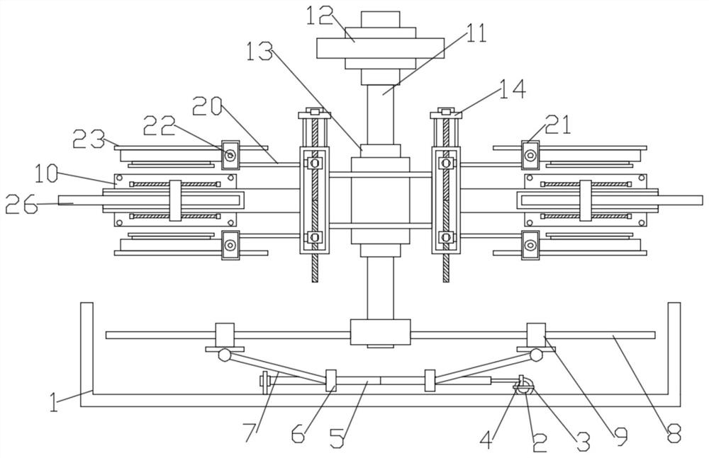
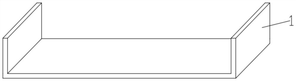
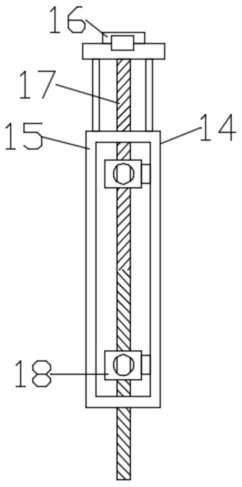
[0021] like Figure 1-2 As shown, in the embodiment of the present invention, a positioning fixture for sewing machine head shell processing includes a base 1 and a column 11, a column 11 is arranged above the base 1, and a mounting seat 13 is fixedly installed in the middle of the column 11. Both sides of 13 are symmetrically provided with a clamping assembly 14 for clamping the shell, the mounting base 13 and the clamping assembly 14 are fixedly connected, and a position adjustment assembly for adjusting the height of the column 11 is provided between the column 11 and the base 1;

[0022] The position adjustment assembly includes a hydraulic cylinder 2, a rack 3 and a gear 4. The hydraulic cylinder 2 is fixedly installed on the upper surface of the base 1, and the telescopic end of the hydraulic cylinder 2 is fixedly connected to the rack 3, and the gear 4 is arranged above the rack 3. , the meshing transmission between the gear 4 and the rack 3, and one end of the gear 4 i...

Embodiment 2

[0029] like Figure 1-2 As shown, in the embodiment of the present invention, a positioning fixture for sewing machine head shell processing includes a base 1 and a column 11, a column 11 is arranged above the base 1, and a mounting seat 13 is fixedly installed in the middle of the column 11. Both sides of 13 are symmetrically provided with a clamping assembly 14 for clamping the shell, the mounting base 13 and the clamping assembly 14 are fixedly connected, and a position adjustment assembly for adjusting the height of the column 11 is provided between the column 11 and the base 1;

[0030] The position adjustment assembly includes a hydraulic cylinder 2, a rack 3 and a gear 4. The hydraulic cylinder 2 is fixedly installed on the upper surface of the base 1, and the telescopic end of the hydraulic cylinder 2 is fixedly connected to the rack 3, and the gear 4 is arranged above the rack 3. , the meshing transmission between the gear 4 and the rack 3, and one end of the gear 4 i...


PUM


Abstract

The invention discloses a positioning clamp for sewing machine head shell machining, belongs to the technical field of sewing machines, and solves the problem that the machining difficulty of a shellis increased due to the fact that an existing device cannot adjust the position of a clamping plate mechanism. The positioning clamp is technically characterized by comprising a base and a stand column; the stand column is arranged above the base; an installation base is fixedly installed in the middle of the stand column; clamping assemblies used for clamping the shell are symmetrically arrangedon the two sides of the installation base; the installation base is fixedly connected with the clamping assemblies; and a position adjusting assembly used for adjusting the height of the stand columnis arranged between the stand column and the base. According to the embodiment of the invention, the position adjusting assembly is arranged, the height of the clamping assemblies is adjusted throughthe arrangement of the position adjusting assembly, shells can be conveniently clamped in different environments, the shell machining efficiency is improved, and meanwhile, the shells of different shapes are clamped and limited through the arrangement of a swing assembly.

Description

technical field [0001] The invention relates to the technical field of sewing machines, in particular to a positioning fixture for processing a sewing machine head shell. Background technique [0002] A sewing machine is a machine that uses one or more sewing threads to form one or more stitches on the sewing material to interweave or sew one or more layers of sewing material. The sewing machine can sew fabrics such as cotton, fiber crops, silk, wool, and artificial fibers, and products such as leather, plastics, and paper. Sewing machines are generally composed of four parts: feeding device, machine base, transmission and accessories. [0003] Chinese patent CN211760065U discloses a positioning fixture for sewing machine head shell processing, including two unilateral fixtures symmetrically distributed on the pallet, the unilateral fixture is provided with a hydraulic cylinder assembly for power supply, and the hydraulic pressure The cylinder assembly is provided with a s...

Claims


Application Information

Patent Timeline
Patent Type & Authority Applications(China)
IPC IPC(8): B23Q3/08B23Q1/25
CPCB23Q3/082B23Q1/25
Inventor 胡粉义
Owner WUJIANG ZHENYU SEWING EQUIP
Why Eureka
Try Eureka