Mobile charging and battery replacing equipment

A charging and exchanging equipment and mobile technology, applied in the field of mobile charging and exchanging equipment, can solve the problems of high input cost and small service coverage, achieve low manufacturing cost, easy to grab and quick-change power battery pack, The effect of reducing energy consumption

Active Publication Date: 2021-03-12
上海融和智电新能源有限公司
View PDF6 Cites 4 Cited by
  • Summary
  • Abstract
  • Description
  • Claims
  • Application Information

AI Technical Summary

Problems solved by technology

[0004] In order to solve the problems of high investment cost and small service coverage of current charging and replacing equipment, the present invention provides a low-cost mobile charging and replacing Equipment, the charging and changing equipment provided by the present invention can not only provide quick battery changing and charging services, but also provide emergency rescue for electromechanical equipment that has broken down due to power exhaustion, with a small footprint, no need for infrastructure, and low cost

Method used


Image

  • Mobile charging and battery replacing equipment
  • Mobile charging and battery replacing equipment
  • Mobile charging and battery replacing equipment

Examples


Embodiment 1

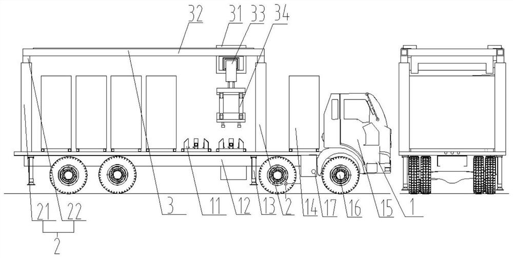
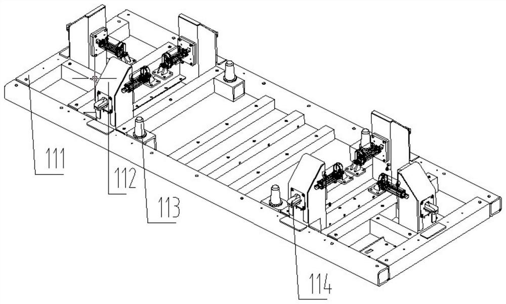
[0049] Such as Figure 2-5 As shown, the mobile charging and replacing equipment provided by the present invention includes: a traveling chassis mechanism 1 with a plurality of battery pack bases 11; a plurality of telescopic columns 2 arranged on the chassis mechanism 1; connected to the upper ends of a plurality of telescopic columns, The vertically and horizontally movable power battery pack replacement mechanism 3 located at the upper end of the plurality of battery pack bases 11 .

[0050] Specifically, the vacancy rate of the plurality of battery pack bases 11 is less than or equal to 50%.

[0051] Further, at least two of the plurality of battery pack bases 11 are empty.

[0052] It should be noted that the present invention does not specifically limit the number of battery pack bases, and those skilled in the art can set the number of battery pack bases to 4, or 5, 6, 7, 8 or more according to actual needs . In actual use, in order to facilitate the operation of bat...

Embodiment 2

[0065] Such as Figure 7-8 As shown, except that the lower structure 342 in the gripper 34 is opened downward, the two sides of the opening end have two floating platforms 3421 inward; the upper end 3441 of the gripper 344 passes through the opening and is placed on the floating platform Except for the floating connection of the lower structure, the others are the same as in Embodiment 1.

[0066] Specifically, the outer diameter of the upper end of the gripper 344 is smaller than the inner diameter of the lower structure, but larger than the distance between the two floating platforms.

[0067] Through the expansion and contraction of the oil cylinder 343 and the floating connection of the gripper 344, the quick-change power battery pack 4 can be smoothly taken out and put down from the battery pack base 11, and the soft connection between the gripper 344 and the lower structure 342 can ensure the power Even if the exhausted old quick-change power battery pack 5 is not on th...


PUM


Abstract

The invention discloses mobile charging and battery replacing equipment, and relates to charging and battery replacing equipment. The equipment comprises: an advancing chassis mechanism with a plurality of battery pack bases; a plurality of telescopic stand columns on the chassis mechanism; and a power battery pack replacement mechanism capable of moving vertically and horizontally, connected to upper ends of the plurality of telescopic stand columns and located at the upper ends of a plurality of battery pack bases. According to the mobile charging and battery replacing equipment provided bythe invention, the conventionally used battery pack bases are mounted on the advancing chassis mechanism, so that the problems that a fixed charging and battery replacing station is large in occupiedarea, needs capital construction, is high in cost and cannot solve the road rescue problem of a fixed charging pile and a fixed battery replacing station are solved. In addition, the mobile charging equipment provided by the invention can be moved to a unified station for centralized management, and the problems of scattered distribution and inconvenient maintenance of the fixed charging piles aresolved.

Description

technical field [0001] The invention relates to the field of charging and changing equipment, in particular to a mobile charging and changing equipment. Background technique [0002] In response to the global call for energy conservation and emission reduction, in recent years, mechanical equipment powered by fuel oil has gradually been replaced by electric mechanical equipment. However, the problems of short battery life, slow charging, and fast battery decay in electromechanical equipment also restrict the application of electromechanical equipment. [0003] At present, there are two main methods to expand the application range of pure electric mechanical equipment: ①. Design the battery pack as a fixed battery pack fixed on the mechanical equipment, adopt the direct charging mode, and build a large number of charging piles. There are a large number of charging piles, which can solve the problem of difficult charging, but still cannot solve the problems of slow charging a...

Claims


Application Information

Patent Timeline
Patent Type & Authority Applications(China)
IPC IPC(8): B60L53/80B60S5/06B60P3/00
CPCB60L53/80B60S5/06B60P3/00Y02T10/70Y02T10/7072
Inventor 蔡宁郭鹏张学文金凯谷杰伟丁习坤来瑞俊吴桢林
Owner 上海融和智电新能源有限公司
Why Eureka
Try Eureka