Supercharge Your Innovation With Domain-Expert AI Agents!

Beam type bogie frame and beam type bogie

A bogie and beam-type technology, applied in the direction of mechanical conveyors, conveyors, motor vehicles, etc., can solve the problem of large size of the bogie, and achieve the effect of reducing the size of the bogie.

Active Publication Date: 2021-03-12
CRRC YANGTZE GRP CO LTD
View PDF13 Cites 0 Cited by
  • Summary
  • Abstract
  • Description
  • Claims
  • Application Information

AI Technical Summary

Problems solved by technology

[0004] In view of this, the purpose of the present invention is to overcome the deficiencies of the prior art. In the first aspect, a beam bogie frame is provided to solve the problem that the bogie of the existing underground pipeline transportation vehicle relies on the guide rail to travel and has a large external dimension. technical problem

Method used


Image

  • Beam type bogie frame and beam type bogie
  • Beam type bogie frame and beam type bogie
  • Beam type bogie frame and beam type bogie

Examples


Embodiment 1

[0035] Such as Figure 4 As shown, urban underground logistics vehicles run in underground pipelines, and drainage ditches for discharging sewage or accumulated water are usually arranged in the pipelines. In the present invention, the top of the drainage ditch is used as the running surface 81 , and the sidewall of the drainage ditch is used as the guiding surface 82 .

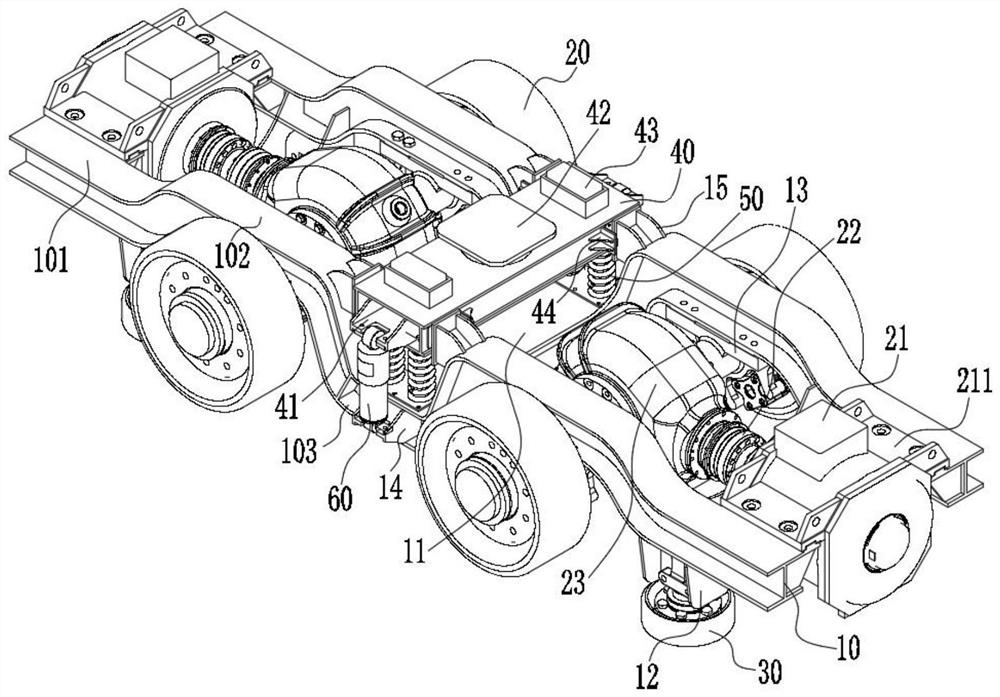
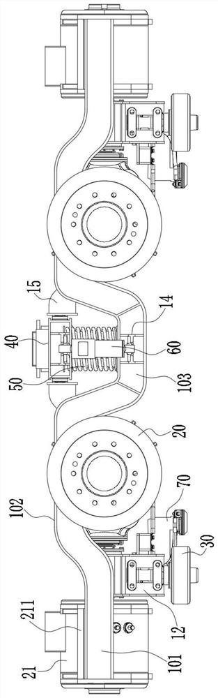
[0036] The invention provides a beam bogie frame, such as Figure 1 to Figure 3 As shown, a beam frame is included, and the beam frame includes longitudinal beams 10 , cross beams 11 and connecting beams 12 . Wherein, the longitudinal beam 10 includes a first straight section 101, a second straight section 102 and a third straight section 103, the middle part of the longitudinal beam 10 is the third straight section 103, and the two ends of the longitudinal beam 10 are the first flat sections. Straight sections 101 , the first straight sections 101 at both ends are arranged symmetrically with respect to the...

Embodiment 2

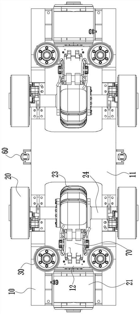
[0042] The present invention also provides a beam bogie, such as Figure 1 to Figure 3 As shown, it includes the beam bogie frame, traveling wheels 20 and guide wheels 30 in the above embodiments. A wheel shaft 24 is connected between the running wheel frame 13 at the bottom of the second straight section 102 between the two longitudinal beams 10 through a bearing, and the wheel shaft 24 is connected with the running wheel 20 after extending outward. As a power bogie, the beam bogie frame is also connected with a driving motor 21 for driving the traveling wheels 20 to walk. The driving motor 21 is connected to a gear box 23 through a coupling 22, and the driving motor 21 drives the gear box 23 to run. The box 23 drives the traveling wheel 20 to travel through the wheel shaft 24 .

[0043] Such as Figure 1 to Figure 3 As shown, specifically, two supporting plates 211 are connected to both sides of the driving motor 21 by welding or bolting, and the supporting plates 211 are ...


PUM


Abstract

The invention discloses a beam type bogie frame and a beam type bogie, relates to the technical field of underground pipeline transportation, and solves the technical problems that a bogie of an existing underground pipeline transportation vehicle depends on a guide rail to run and is large in boundary dimension. The beam type bogie comprises the beam type frame, a swing bolster used for being connected with a vehicle body is connected to the beam type frame, and a walking part and a guiding part are arranged at the bottoms of the two sides of the beam type frame respectively. The drainage ditches in a pipeline are ingeniously used as guide rails of the bogie, the walking parts at the bottoms of the two sides of the beam type frame are provided with walking wheels and then walk on the walking faces of the drainage ditches, the guide parts at the bottoms of the two sides of the beam type frame are provided with guide wheels and then walk on the guide faces of the drainage ditches, and extra guide rails do not need to be arranged. Besides, through reasonable arrangement of the beam type frame, the swing bolster, a spring assembly, a shock absorber and a current collector on the beamtype frame, the boundary dimension of the bogie is reduced, and overall design of an underground pipeline is facilitated.

Description

technical field [0001] The invention relates to the technical field of underground pipeline transportation, in particular to a beam bogie frame and a beam bogie. Background technique [0002] With the increasing development of urban underground logistics system, the design of underground pipeline transportation vehicles has gradually become an important research topic. In the prior art, when an urban underground logistics vehicle runs in an underground pipeline, the wheels on the vehicle bogie usually adopt a rubber wheel structure, which can effectively reduce the impact force on the pipeline when the vehicle is running. However, the wheels with rubber tire structure need to be provided with guide wheels on the vehicle, which requires separate guide rails for guiding the guide wheels in the pipeline. The design and construction of guide wheels and guide rails is complicated, and the setting of guide rails also increases. the construction cost of the pipeline. [0003] In ...

Claims


Application Information

Patent Timeline
Patent Type & Authority Applications(China)
IPC IPC(8): B62D63/02B62D63/04B65G35/00F16L55/26F16L55/28
CPCB62D63/02B62D63/04B65G35/00F16L55/26F16L55/28
Inventor 刘爱文侯建云梅琨罗辉柯晓乐冯晔王全虎黄美林苏利杰张良威
Owner CRRC YANGTZE GRP CO LTD
Features
  • R&D
  • Intellectual Property
  • Life Sciences
  • Materials
  • Tech Scout
  • Unparalleled Data Quality
  • Higher Quality Content
  • 60% Fewer Hallucinations
Learn More