Ripple-forming externally-wrapped corrugated steel-concrete composite beam and construction method and application thereof

A technology of concrete and composite beams, applied in the direction of joists, girders, truss beams, etc., can solve the problems of building stability and seismic performance damage, composite beams lose bearing capacity, and reduce building integrity, etc., to achieve enhanced collapse resistance, The effect of overcoming the insufficient shear bearing capacity and increasing the shear capacity

Inactive Publication Date: 2021-03-12
JIANGNAN UNIV
View PDF8 Cites 1 Cited by
  • Summary
  • Abstract
  • Description
  • Claims
  • Application Information

AI Technical Summary

Problems solved by technology

However, the existing corrugated steel-concrete composite beams still have the following problems: First, the bending capacity of the existing corrugated steel-concrete composite beams is mainly controlled by the steel bottom plate. Once the bottom plate is damaged, the composite beam will be damaged. Loss of bearing capacity; second, in the earthquake environment, due to the presence of transverse shear, the composite beam is prone to separation between the outer steel floor part and the concrete
The above problems have greatly reduced the integrity of the building and caused damage to the stability and seismic performance of the building.

Method used


Image

  • Ripple-forming externally-wrapped corrugated steel-concrete composite beam and construction method and application thereof
  • Ripple-forming externally-wrapped corrugated steel-concrete composite beam and construction method and application thereof
  • Ripple-forming externally-wrapped corrugated steel-concrete composite beam and construction method and application thereof

Examples


Embodiment 1

[0043] Example 1: A corrugated steel-concrete composite beam covered with waves

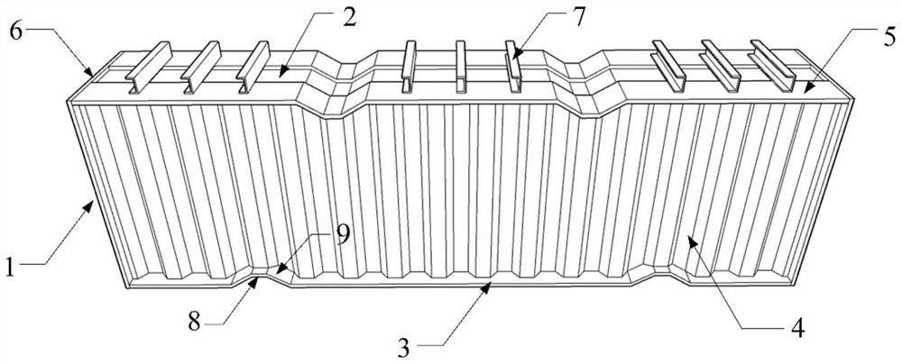
[0044] like Figure 1-3 , a corrugated steel-concrete composite beam covered with waves, comprising a steel skeleton 1 and corrugated concrete 2 filled inside the steel skeleton 1 .

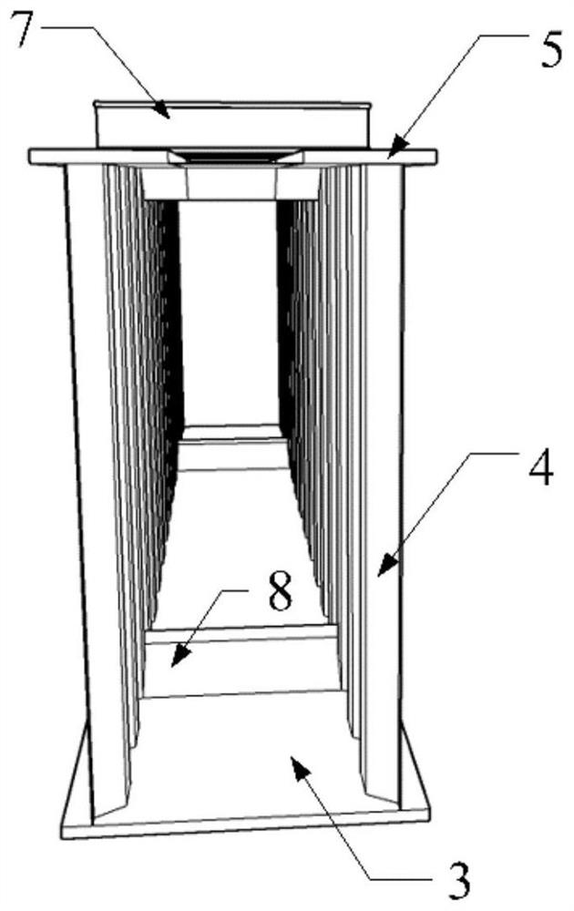
[0045] The steel skeleton 1 includes a corrugated bottom plate 3, two corrugated steel webs 4 distributed along the beam length direction and vertically connected to the corrugated bottom plate 3, parallel to the corrugated bottom plate 3 and vertically connected to the two corrugated webs 4 respectively two corrugated top plates 5, and two end plates 6 which are located at both ends of the composite beam and are vertically connected to the corrugated bottom plate 3, the corrugated web 4 and the corrugated top plate 5; the corrugated top plate 5 is welded with several Shear channel steel 7.

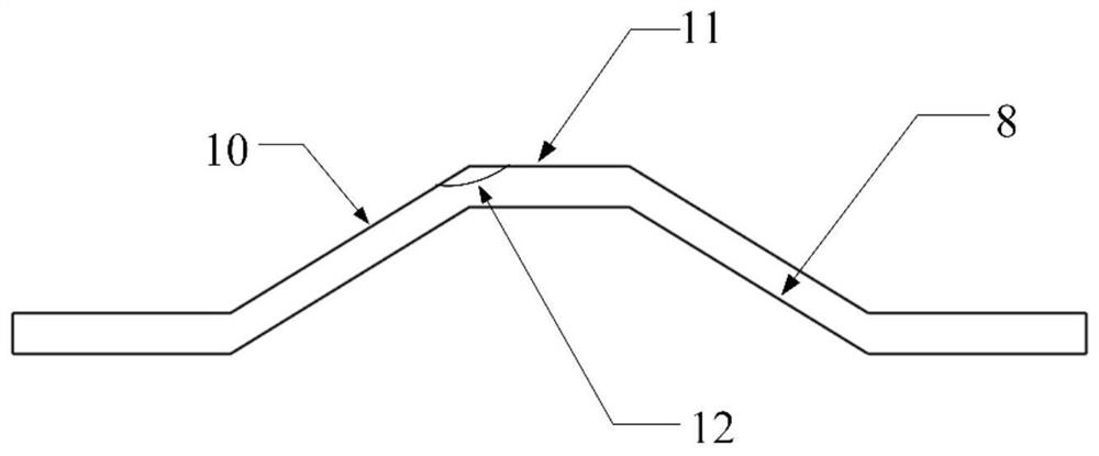
[0046] The corrugated bottom plate 3 is provided with an inverted "U"-shaped wave 8; the inverted "U"-shaped wave 8 is not ...

Embodiment 2

[0049] Example 2: Construction method of corrugated steel-concrete composite beam with corrugated outsourcing

[0050] Specific steps are as follows:

[0051] (1) Making steel skeleton 1

[0052] Corrugation is carried out on the corrugated bottom plate 3 and the corrugated top plate 5, and a notch matching the inverted “U”-shaped wave 8 is cut on the corrugated web 4 corresponding to the inverted “U”-shaped wave 8. The cut corrugated web 4 is vertically welded on both sides of the corrugated bottom plate 3, and no welding is performed at the inverted "U"-shaped corrugation 8. The corrugated top plate 6 is vertically welded above the corrugated web 4, and the inverted “U”-shaped wave 8 on the corrugated top plate 6 is not welded. Weld the shear channel steel 7 to the two corrugated top plates 5, the welding method of the shear channel steel 7 is: between the inverted "U" wave 8 or between the inverted "U" wave 8 and the end plate 6 Three shear-resistant channel steels 7 are...

Embodiment 3

[0055] Example 3: Detection of corrugated steel-concrete composite beams with corrugated outsourcing

[0056] Specific steps are as follows:

[0057] Using C40 ordinary concrete as the corrugated concrete material, Q345 as the steel material, and non-stick film of plastic material, referring to Examples 1-2, a corrugated steel-concrete composite beam covered with corrugation was prepared. Among them, the span of the corrugated steel-concrete composite beam covered with corrugations is 3.6m, and the section size is 200mm×520mm; the section size of the corrugated bottom plate is 220mm×4mm; the section size of the web plate is 450mm×3mm; It is 80mm×6mm; the size of the end plate is 220mm×460mm×6mm; there are two inverted “U” waves on the corrugated bottom plate, one of which is between the center of the inverted “U” wave and the closer end plate The distance between the other inverted "U" wave and the closer end plate is one-fifth of the beam length; the wave top plate is also p...


PUM

PropertyMeasurementUnit
lengthaaaaaaaaaa

Abstract

Provided is a ripple-forming externally-wrapped corrugated steel-concrete composite beam. The composite beam comprises a steel framework (1) and wavy concrete (2); the steel framework (1) comprises abottom plate, a web plate, a top plate and an end plate; the beam is characterized in that the bottom plate is a corrugated bottom plate (3), the web plate is a corrugated web plate (4), and the top plate is a corrugated top plate (5); and a plurality of inverted U-shaped waves (8) are arranged on the corrugated bottom plate (3) and the corrugated top plate (5). Inverted-U-shaped wavy protrusionscan deform greatly in the loaded straightening process, so that the deformability of the composite beam under the earthquake action is improved, and the collapse resistance is enhanced; the wave starting position of the corrugated steel composite beam is covered with a non-sticky film, and the corrugated steel composite beam is not bonded with concrete locally, so that the deformation of the inverted-U-shaped wavy protrusions is not affected, and the deformability of the composite beam in an earthquake is further improved; and the bonding of two interfaces is increased through the corrugated web plate and shear-resistant channel steel, so that the situation that a steel plate and the concrete work together is guaranteed.

Description

technical field [0001] The invention relates to the field of building technology and structural engineering technology, in particular to a corrugated steel-concrete composite beam covered with corrugated waves and its construction method and application. Background technique [0002] Although steel-concrete composite beams have obvious application advantages, there are still some problems in the force, such as slippage between concrete and steel, and insufficient longitudinal shear resistance of concrete. In order to improve the deficiencies of ordinary composite beams, outsourcing steel-concrete composite beams came into being. Outer-clad steel-concrete composite beam refers to a new type of composite beam that welds or cold-bends steel plates into a U shape and fills concrete inside. It not only has higher bearing capacity, rigidity and ductility, but also has a When the U-shaped steel is exposed to fire on one side, the internal concrete can absorb the heat on the steel ...

Claims


Application Information

Patent Timeline
Patent Type & Authority Applications(China)
IPC IPC(8): E04C3/20
CPCE04C3/20
Inventor 邹昀谢梦洁王城泉陈明吴艺超
Owner JIANGNAN UNIV
Why Eureka
Try Eureka