Anchor rod drilling machine with geological recognition function

A rock bolt rig, functional technology, applied in bolt installation, directional drilling, earthwork drilling and mining, etc., can solve problems such as unfavorable drilling work, safety accidents, difficult geological real-time grasp, etc., to improve convenience, practicability, and guarantee The effect of safety and stability

Active Publication Date: 2021-03-12
CHINA RAILWAY TUNNEL GROUP CO LTD +1
View PDF9 Cites 1 Cited by
  • Summary
  • Abstract
  • Description
  • Claims
  • Application Information

AI Technical Summary

Problems solved by technology

[0002] Anchor Drilling Rigs, also known as Anchor Drilling Rigs in some places, are roadway bolting equipment used in coal mines, which can improve support effects and reduce costs , Accelerate the speed of roadway formation, reduce the amount of auxiliary transportation, reduce labor intensity, and improve the utilization rate of the roadway section. The bolter is the key equipment for bolting, and it affects the quality of bolting. , the orientation, depth, and diameter accuracy of the bolt hole, as well as the installation quality of the bolt, as well as the personal safety, labor intensity and working conditions of the operator. Among them, the pneumatic rock bolt rig is widely used due to its small size and convenient use. However, when the existing pneumatic rock bolt rig is used, it is only driven by the outrigger for lifting and lowering, which lacks the lifting protection for the equipment, so that the equipment is easy to tilt or collapse during use, which will cause certain safety accidents and have a certain degree of danger. , and when the existing rock bolter is drilling, it is difficult to identify the geological conditions of the rock where the hole is being drilled in real time, and it is difficult to grasp the geology in real time, which is not conducive to the subsequent drilling work, and has certain limitations

Method used


Image

  • Anchor rod drilling machine with geological recognition function
  • Anchor rod drilling machine with geological recognition function
  • Anchor rod drilling machine with geological recognition function

Examples


Embodiment approach

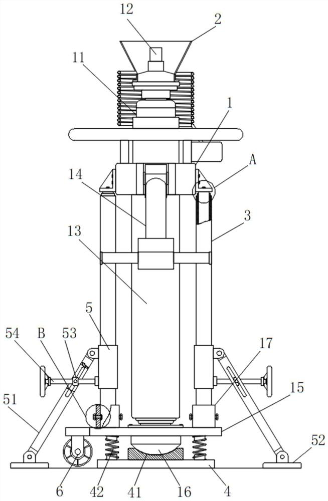
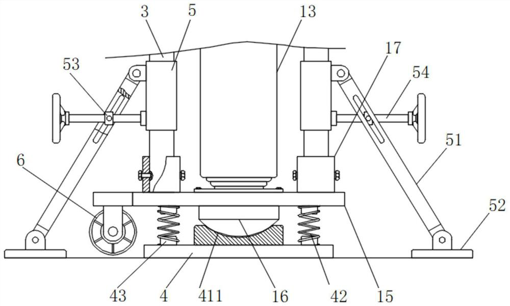
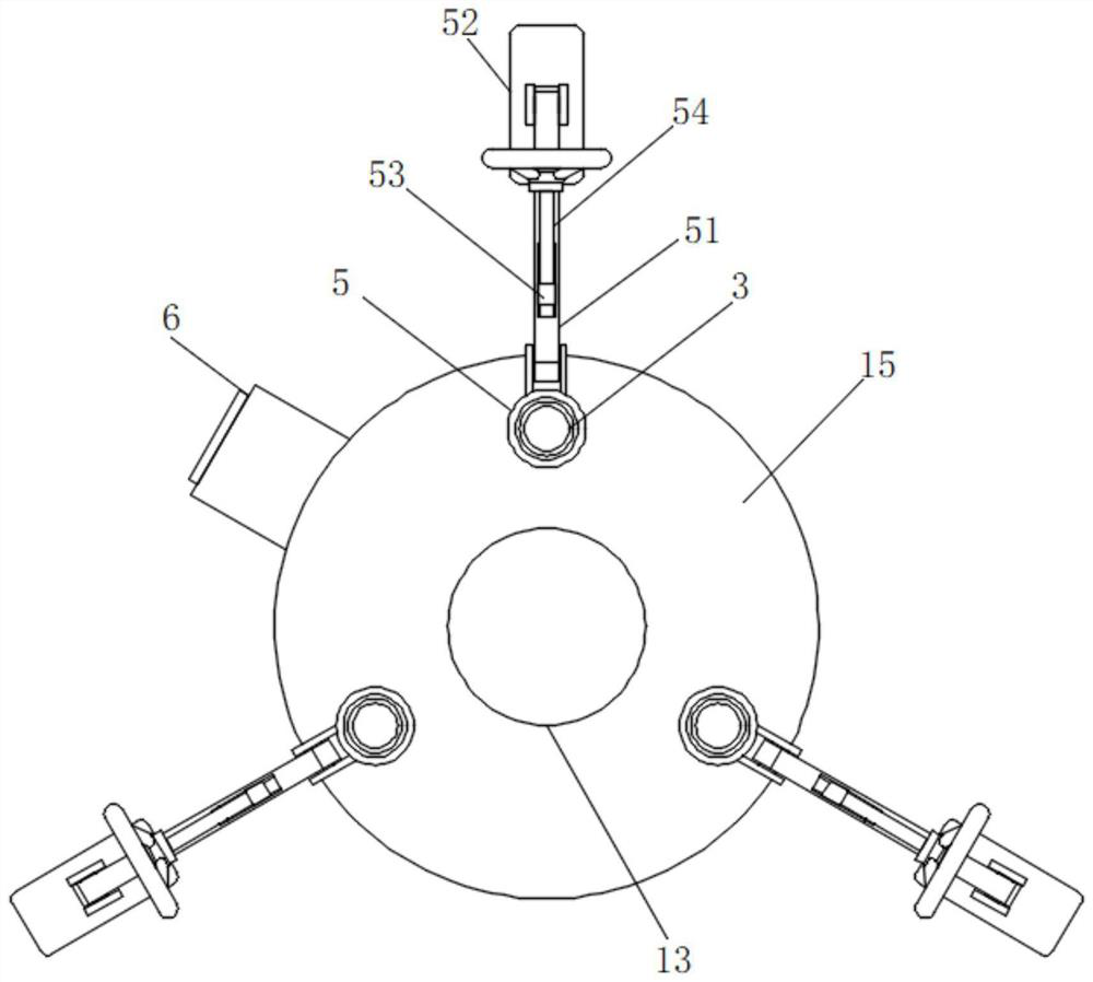
[0035] The implementation method is as follows: insert the hexagonal drill pipe into the hexagonal hole of the drill pipe joint 12, let the drill pipe slowly rotate, use the expansion and contraction of the outrigger 13 to drive the drill pipe to rise slowly, and then the drilling work can be carried out, and by driving Three sets of telescopic guide rod assemblies 3 are arranged outside the assembly 11, and the bottom end of the outer sleeve rod 31 is fixedly connected with the bottom connecting plate 15 through the installation sleeve 17, so that when the bottom end of the supporting leg 13 drives the assembly 11 to go up and down, Utilizing the sliding cooperation of the sliding rod 33, the lining rod 32 and the outer rod 31, the lifting and lowering of the drive assembly 11 can be guided and supported, so that the equipment can work more smoothly when lifting, thereby ensuring the stable operation of the equipment without accidental tilting. safety accidents, and by install...


PUM


Abstract

The invention discloses an anchor rod drilling machine with a geological recognition function. The anchor rod drilling machine comprises a pneumatic anchor rod drilling machine body, wherein the pneumatic anchor rod drilling machine body comprises a driving assembly; a drill rod connector is in transmission connection with the top of the driving assembly; a rock mass collecting and observing device is arranged at the top of the driving assembly; supporting legs are arranged at the bottom of the driving assembly; an operating arm assembly is rotationally installed on one side of the driving assembly; a bottom connecting plate is fixedly connected to the bottoms of the supporting legs through bolt assemblies; and a supporting base is arranged at the bottom of the bottom connecting plate. According to the anchor rod drilling machine, through sliding fit of a sliding rod, a lining rod and an outer sleeve rod, lifting of the driving assembly is guided and supported, so that the equipment ismore stable during working and lifting; and a ground grabbing plate at the bottoms of three inclined supporting rods is in contact with the ground for supporting, so that the stability of overall placement of the equipment is guaranteed, then the convenience and practicability of the equipment are greatly improved, and the safety of the equipment is guaranteed.

Description

technical field [0001] The invention relates to the technical field of rock bolts, in particular to a rock bolt with geological identification function. Background technique [0002] Anchor Drilling Rigs, also known as Anchor Drilling Rigs in some places, are roadway bolt support equipment used in coal mines. It has very prominent advantages in improving the utilization rate of the roadway section. The bolter is the key equipment for bolting, which affects the quality of the bolting, the orientation, depth, and diameter of the bolt hole, and the The installation quality of the rod also involves the personal safety of the operator, labor intensity and working conditions. Among them, the pneumatic rock bolter is widely used because of its small size and convenient use. The outriggers are driven up and down, and there is a lack of lifting protection for the equipment, so that the equipment is easy to tilt or collapse during use, which will cause certain safety accidents and ha...

Claims


Application Information

Patent Timeline
Patent Type & Authority Applications(China)
IPC IPC(8): E21B7/02E21B7/04E21B15/00E21B15/04E21B21/00E21B21/01E21B47/00E21D20/00
CPCE21B7/02E21B7/04E21B15/003E21B15/04E21B47/00E21B21/00E21B21/01E21D20/003
Inventor 马亮冯欢欢杨露伟王亚锋杨延栋张艳军彭怀炀曹耀祖陈阳宿源麟孙六成王文超
Owner CHINA RAILWAY TUNNEL GROUP CO LTD
Why Eureka
Try Eureka