Vacuum drying furnace
A technology of vacuum drying furnace and vacuum device, which is applied in the direction of drying solid materials, drying solid materials without heating, drying, etc., which can solve the problems of unguaranteed sealing at the feed inlet, increased energy consumption, and inability to effectively maintain the vacuum degree, etc. problems, to achieve the effect of ensuring vacuum drying effect, solving sealing problems, and avoiding insufficient drying
- Summary
- Abstract
- Description
- Claims
- Application Information
AI Technical Summary
Problems solved by technology
Method used
Image
Examples
Embodiment 1
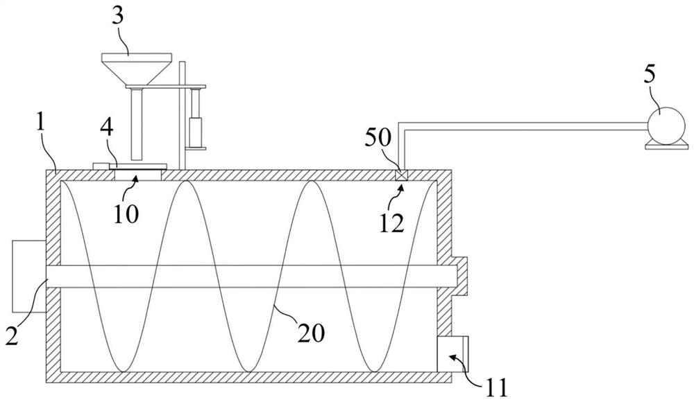
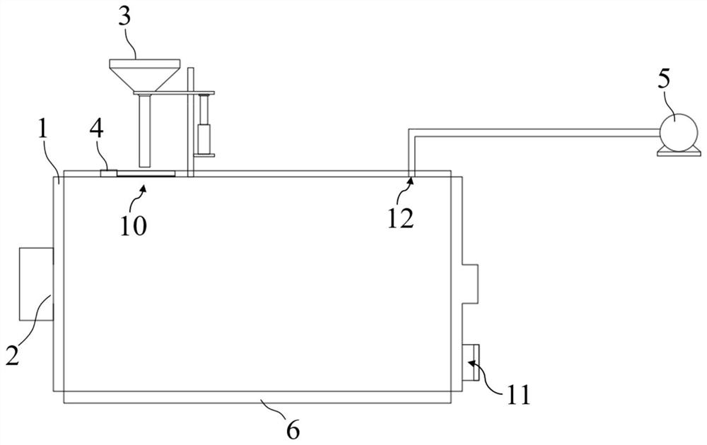
[0047] The vacuum drying furnace of this embodiment, including,
[0048] The furnace body 1, which is horizontally, and the top side is formed on the top side, and the on the other side forms an air outlet 12, and the bottom side is formed.
[0049] The stirring mechanism 2 is provided in the furnace body 1, and the material in the furnace body 1 is stirred;
[0050] Vacuum device 5, which is in communication with the air outlet 12 of the furnace body 1, and maintain a negative pressure environment inside the furnace body 1;
[0051] Also included, the feeding device 3 includes:
[0052] The fraft 30, which is a funnel-like shape, composed of the flange port 300 and the vertical communication with the tube 301 at the bottom of the flange 300, and the fracture 30 is placed directly above the feed port 10;
[0053] The lifting mechanism 31, which is arranged on the side of the fed struggle, and controls the lifting of the fighter 30; and
[0054] The sealing gate 4 is disposed at th...
Embodiment 2
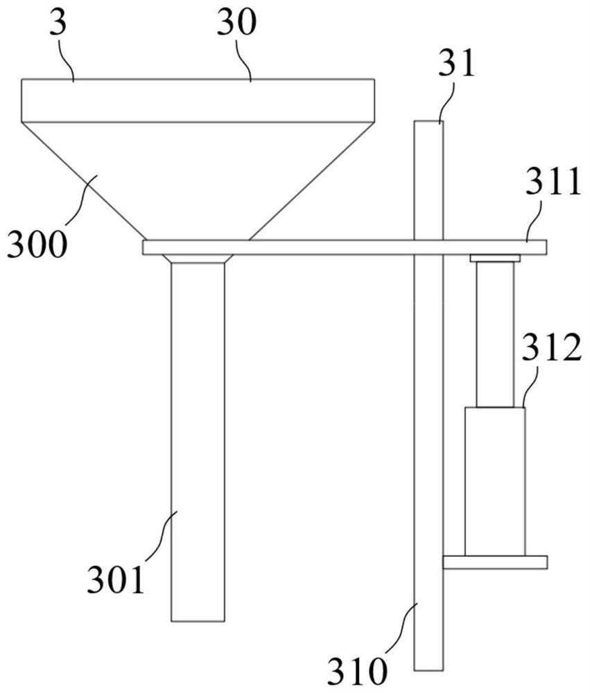
[0059] The vacuum drying furnace of the present embodiment is further improved on the basis of Example 1, and the lifting mechanism 31 includes:
[0060] The guide rod 310 is disposed vertically, and is fixed to the top of the furnace body 1 next to the fed strip 30;
[0061] The moving clip 311, the horizontal setting, slides on the guide rod 310, and one end is sandwiched 30;
[0062] The drive 312 is driven to drive the moving clip 311 lift.
[0063] Such as figure 2 As shown, the guide rod 310 performs limit and orientation to the motion trajectory of the moving clip 311, the guide rod 310 of the present embodiment is a quadrush, the middle portion of the moving clip 311, the hole type matches the four prismatic cross-sectional shape, and the sleeve is guided On the rod 310, thereby, the moving clip 311 can only rise and fall under the guide rod 310; the moving clip 311 is a clamping portion, which can clamp the flange 300 of the fed strip 30, and the fighter 30 can be detach...
Embodiment 3
[0065] The vacuum drying furnace of the present embodiment is further improved on the basis of Example 2, and the mixing mechanism 2 includes:
[0066] The shaft is disposed in the middle of the furnace body 1;
[0067] Spiral blades 20, which are fixed to the shaft.
[0068] Such as figure 1 As shown, the shaft is disposed on the center axis of the furnace body 1, driven by the drive device, and the spiral blade 20 also rotates in the rotation of the shaft, during the drying process, the spiral blade 20 can be cut when rotating Mud and drive the sludge movement, thereby ensuring sufficient agitation of sludge and crushing in the drying process, avoiding drying in sufficient agglomeration.
[0069] Further, when the drying is completed, the material guide can be sent from the discharge port 11 by controlling the direction of rotation of the spiral blade 20, and the principle of the principle of the helix feeder can be used.
PUM
 Abstract
Description
Claims
Application Information
 - R&D
- Intellectual Property
- Life Sciences
- Materials
- Tech Scout
- Unparalleled Data Quality
- Higher Quality Content
- 60% Fewer Hallucinations
Browse by: Latest US Patents, China's latest patents, Technical Efficacy Thesaurus, Application Domain, Technology Topic, Popular Technical Reports.
© 2025 PatSnap. All rights reserved.Legal|Privacy policy|Modern Slavery Act Transparency Statement|Sitemap|About US| Contact US: help@patsnap.com


