
Reconstruction method and system based on high-speed visual diagnosis and BP neural network

A BP neural network and vision technology, applied in neural learning methods, biological neural network models, neural architectures, etc., can solve problems such as slow reconstruction speed, and achieve the effect of improving accuracy, reducing computational complexity, and low system resource consumption

Active Publication Date: 2021-03-12
CHONGQING UNIV OF POSTS & TELECOMM
View PDF9 Cites 2 Cited by
  • Summary
  • Abstract
  • Description
  • Claims
  • Application Information

AI Technical Summary

Problems solved by technology

In the process of conversion, the homography matrix of the conversion will be calculated. In traditional algorithms such as Zhang Zhengyou calibration and Cai's calibration, the homography matrix is ​​calculated, so the reconstruction speed is slow.

Method used


Image

  • Reconstruction method and system based on high-speed visual diagnosis and BP neural network
  • Reconstruction method and system based on high-speed visual diagnosis and BP neural network
  • Reconstruction method and system based on high-speed visual diagnosis and BP neural network

Examples


Embodiment 1

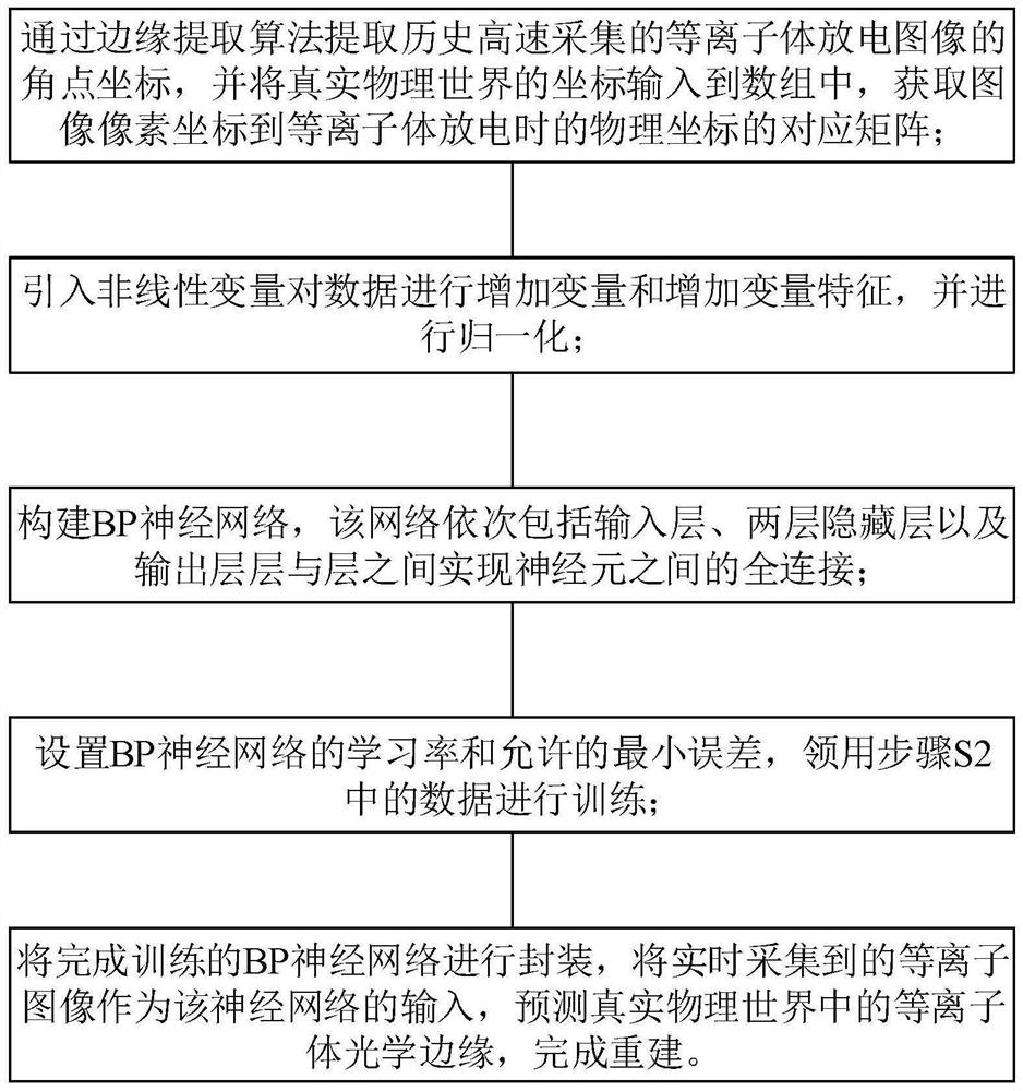
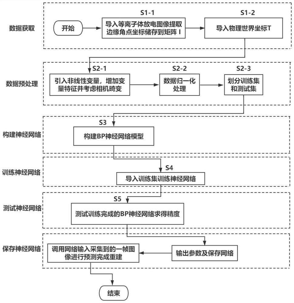
[0046] This embodiment proposes a specific implementation method of a reconstruction method based on high-speed visual diagnosis and BP neural network.

[0047] In this embodiment, a shot of plasma discharge data is taken as an example to illustrate the specific implementation steps of the present invention, and the goal is to perform plasma optical edge reconstruction on a plasma image collected in one frame. Record the plasma image corner coordinate matrix to be collected as I, I contains 35,000 coordinate points, and then record the obtained world coordinate point matrix as T.

[0048]Plasma edge pixels typically have high brightness values, indicating high global contrast, specifically, the effective value of a pixel by the way it contrasts with other pixels. For an image I with m×n pixels, the saliency value s(x, y) of a pixel I(x, y) is defined as:

[0049]

[0050] In order to reduce the overall calculation time, the above formula is simplified:

[0051]

[0052...

Embodiment 2

[0062] This embodiment proposes a reconstruction system based on high-speed visual diagnosis and BP neural network. The system includes a data acquisition module, a plasma discharge image angular coordinate acquisition module, a corresponding matrix acquisition module, a feature transformation module, a normalization module, and a neural network. Network model; where:

[0063] The data acquisition module is used to acquire real-time data and training data, and the acquired real-time data is;

[0064] The plasma discharge image angular coordinate acquisition module extracts the angular point coordinates of the historical high-speed collected plasma discharge image through an edge extraction algorithm;

[0065] The corresponding matrix acquisition module is used to acquire the corresponding matrix from the image pixel coordinates to the physical coordinates during plasma discharge;

[0066] The feature transformation module performs nonlinear changes on the acquired data, and t...


PUM


Abstract

The invention belongs to the field of EAST plasma optical edge reconstruction, and particularly relates to a reconstruction method and system based on high-speed visual diagnosis and a BP neural network, and the method comprises the steps: collecting the corner coordinates of a plasma discharge image, and obtaining a corresponding matrix from the pixel coordinates of the image to the physical coordinates during plasma discharge; introducing non-linear variables to add variables and variable characteristics to the data; constructing a BP neural network, setting a learning rate and an allowableminimum error of the BP neural network, and performing training by utilizing data; packaging the trained BP neural network, taking real-time data as the input of the neural network, and predicting theplasma optical edge in the real physical world. According to the method, the problem that the plasma optical edge is reconstructed in the process of predicting the coordinates of the corner points inthe next unknown time period on the EAST device is solved.

Description

technical field [0001] The invention belongs to the fields of machine learning and EAST plasma optical edge reconstruction, and in particular relates to a reconstruction method and system based on high-speed visual diagnosis and BP neural network. Background technique [0002] Optimizing plasma discharge requires accurate control of parameters such as plasma configuration. When these parameters cannot be directly measured, it is necessary to use external measurement data to reconstruct the plasma edge to provide optimal control parameters. At the same time, the analysis of physical diagnostic data requires accurate and reliable plasma edge reconstruction results as a reference. Therefore, it is of great significance to carry out accurate and fast reconstruction of the optical edge of EAST plasma. [0003] With the rapid development of computer vision technology and high-speed CCD camera software and hardware technology, it has become an important trend to use high-speed com...

Claims


Application Information

Patent Timeline
Patent Type & Authority Applications(China)
IPC IPC(8): G06K9/46G06K9/62G06N3/04G06N3/08G06T3/60
CPCG06N3/084G06T3/604G06V10/44G06N3/045G06F18/214
Inventor 郭子涵张恒杭芹黄耀陈大龙沈飊肖炳甲吕雪李佳怡刘洋
Owner CHONGQING UNIV OF POSTS & TELECOMM
Learn More