
Method and device for obtaining optimal parameters of direct-current transmission system current limiter

A DC transmission system and optimal parameter technology, applied in circuit devices, emergency protection circuit devices, AC network circuits, etc., can solve the problem of increasing the difficulty and cost of DC circuit breaker design, affecting the stable operation of DC networks, and increasing the construction of converter stations Cost and other issues

Pending Publication Date: 2021-03-12
YUNNAN POWER GRID CO LTD ELECTRIC POWER RES INST
View PDF6 Cites 2 Cited by
  • Summary
  • Abstract
  • Description
  • Claims
  • Application Information

AI Technical Summary

Problems solved by technology

[0003] At present, one of the main solutions for DC side faults is to configure converters and DC circuit breakers with fault isolation capabilities on the DC line, and converters with fault isolation functions will not only increase the construction cost of the converter station, but also require Blocking all converters in the DC network will affect the stable operation of the DC network, and because fault detection and the action of the DC circuit breaker take time, the fault current often has risen rapidly, which will make the requirements of the DC circuit breaker for the breaking capacity Further improvement, therefore, the application of DC circuit breakers is limited by the cut-off capacity, especially in multi-terminal DC transmission systems with complex capacitor discharge paths, which increases the design difficulty and cost of DC circuit breakers. Therefore, it is necessary to choose a suitable current limiting solution to avoid the above problems

Method used


Image

  • Method and device for obtaining optimal parameters of direct-current transmission system current limiter
  • Method and device for obtaining optimal parameters of direct-current transmission system current limiter
  • Method and device for obtaining optimal parameters of direct-current transmission system current limiter

Examples


Embodiment Construction

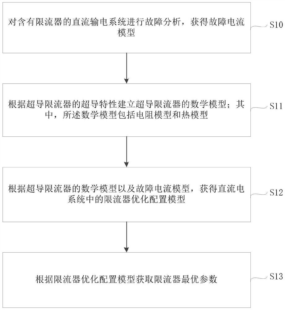
[0085] In order to make the above objects, features and advantages of the present application more obvious and understandable, the present application will be further described in detail below in conjunction with the accompanying drawings and specific implementation methods.

[0086] This application provides a method and device for obtaining optimal parameters of a current limiter in a direct current transmission system, so as to obtain the optimal parameter configuration of a current limiter in a direct current transmission system, and solve the problem that is often encountered when configuring a superconducting current limiter in a direct current transmission system Simplify the model of the superconducting current limiter, only consider its steady-state resistance, ignore the coupling relationship between current and resistance and the cost of the superconducting material during the resistance conversion process, so it is difficult to obtain a superconducting current limite...


PUM


Abstract

The embodiment of the invention provides a method and device for obtaining the optimal parameters of a direct-current transmission system current limiter, wherein the method comprises the steps of firstly carrying out fault analysis on a DC power transmission system comprising a current limiter, and obtaining a fault current model; establishing a mathematical model of the superconducting current limiter according to the superconducting characteristics of the superconducting current limiter, wherein the mathematical model comprises a resistance model and a thermal model; then, according to themathematical model and the fault current model of the superconducting current limiter, obtaining an optimal configuration model of the current limiter in the direct current system; and finally, obtaining the optimal parameters of the current limiter according to the optimal configuration model of the current limiter. The optimal parameters obtained by adopting the above scheme can effectively reduce the maximum fault removal capacity of a direct-current circuit breaker, increase the fault response time of the system, ensure the correctness and reliability of the action of the direct-current circuit breaker, and the method and the device have important significance for the direct-current power transmission system.

Description

technical field [0001] The present application relates to the technical field of direct current transmission technology, in particular to a method and device for obtaining optimal parameters of a current limiter in a direct current transmission system. Background technique [0002] DC transmission technology has the advantages of independent control of active power and reactive power, and no risk of commutation failure. Therefore, DC transmission technology has a wide range of applications in new energy grid integration and regional grid interconnection. However, due to the small damping and response coefficient of the DC transmission system, when a short-circuit fault occurs on the DC side of the DC transmission system, the fault will develop rapidly, resulting in a short-circuit current that is more than ten times or even dozens of times the rated current of the system. Therefore, the rapid removal of faults on the DC side has become a difficult point in the research of DC...

Claims


Application Information

Patent Timeline
Patent Type & Authority Applications(China)
IPC IPC(8): H02H7/26H02H3/36
CPCH02H7/268H02H3/36H02J2203/20
Inventor 邢超奚鑫泽刘明群李胜男何鑫徐志卢佳向川
Owner YUNNAN POWER GRID CO LTD ELECTRIC POWER RES INST
Features
  • Generate Ideas
  • Intellectual Property
  • Life Sciences
  • Materials
  • Tech Scout
  • Unparalleled Data Quality
  • Higher Quality Content
  • 60% Fewer Hallucinations
Learn More