Friction stir additive device and additive manufacturing method

A technology of friction stirring and stirring head, which is applied in the direction of manufacturing tools, non-electric welding equipment, welding equipment, etc., can solve the problems of low efficiency of intermittent supply, achieve the effect of improving stability and avoiding follow-up

Active Publication Date: 2021-03-16
安徽万宇机械设备科技有限公司
View PDF10 Cites 19 Cited by
  • Summary
  • Abstract
  • Description
  • Claims
  • Application Information

AI Technical Summary

Problems solved by technology

[0006] Therefore, the technical problem to be solved by the present invention is to overcome the defect of low intermittent supply efficiency in the friction stir additive process in the prior art, so as to provide a friction stir additive device and additive manufacturing method

Method used


Image

  • Friction stir additive device and additive manufacturing method

Examples


Embodiment 1

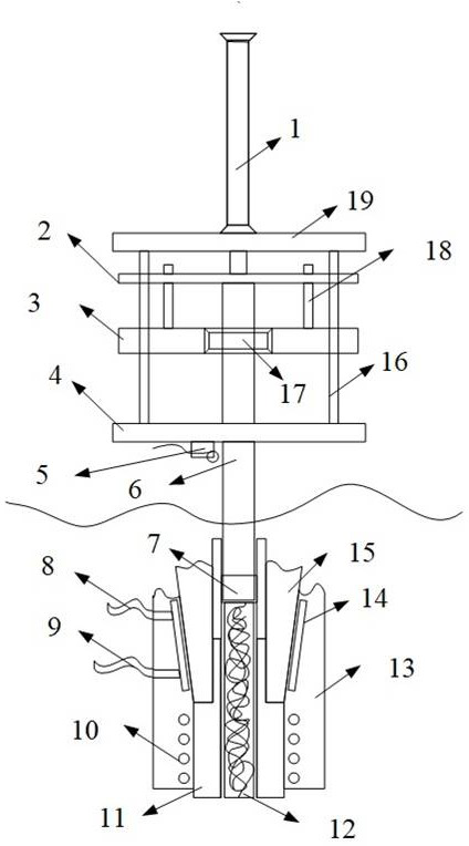
[0040] Such as figure 1 As shown, this embodiment provides a friction stir additive device, which is suitable for providing an additive structure to the substrate to be added, which includes a stirring head 11 and a knife handle 15, and is sleeved on the stirring head 11 and the shaft sleeve 13 outside the handle 15, wherein the stirring head 11 is fixed on the handle 15, and the handle 15 is driven by the main shaft (not shown) of the friction stirring additive device to drive the stirring head 11 Rotate, the connection mode of described mixing head, handle of a knife and main shaft all adopts the conventional connection mode in this field; Described mixing head 11 and the hollow cavity body that communicates with each other in the handle of a knife 15; Specifically, described hollow cavity The body has an opening at the working end of the stirring head 11, wherein the working end refers to the end where the stirring head 11 is in contact with the substrate to be added, namel...

Embodiment 2

[0050] This embodiment also provides an additive manufacturing method, using the friction stir additive device described in Embodiment 1, the additive manufacturing method includes the following steps:

[0051] The wire feeder feeds the wire into the hollow cavity, so that the wire is continuously accumulated, and when the wire is accumulated to a predetermined level, the wire feeding is stopped;

[0052] Then the cylinder pushes the piston guide rod to press down so that the wire in the cavity is continuously compressed and forms a cylinder; at this time, the stirring head is started to rotate, and under the pressure of the cylinder, the compacted wire and the inner wall of the cavity of the stirring head are tightly Combined together, the compacted wire can rotate together when the stirring head rotates. At this time, the compacted wire in the cavity rubs against the material to generate heat and soften to achieve material addition;

[0053] When the wire in the cavity is us...


PUM


Abstract

The invention relates to the technical field of friction stir welding, in particular to a friction stir additive device and an additive manufacturing method. According to the friction stir additive device, hollow cavities which communicate with each other are formed in a stirring head and a knife handle, and the hollow cavity in the working end of the stirring head is provided with an opening; a wire is provided for the hollow cavities through a wire feeder; an extrusion part moves in the hollow cavities to extrude the wire, the wire is extruded into a bar to achieve friction heat production,and therefore, friction stir additive manufacturing is achieved, and continuous supply of materials during feeding can be achieved. By arranging a guide support to bear the extrusion part and providesliding support for an auxiliary plate, the auxiliary plate can be connected with a piston guide rod in a clamped mode, circumferential rotation of the piston guide rod is limited, and therefore, follow-up of a piston and the piston guide rod in the extrusion hollow cavity is avoided, and stability is improved.

Description

technical field [0001] The invention relates to the technical field of friction stir welding, in particular to a friction stir additive device and an additive manufacturing method. Background technique [0002] With the development of engineering technology, traditional subtractive processing such as turning, milling, planing and grinding can no longer meet engineering needs. Therefore, additive processing provides a new processing idea. At present, there are many methods of metal additives, including laser sintering, EDM accumulation, etc., but these methods require the material to be melted and then solidified to form, which increases the probability of secondary defects in the material and reduces the mechanical properties of the material. To this end, a solid-state additive technology-friction stir additive is proposed. [0003] When using friction stir additives, the raw material is usually filament or granular material. However, these raw materials cannot participate...

Claims


Application Information

Patent Timeline
Patent Type & Authority Applications(China)
IPC IPC(8): B23K20/12B23K20/26
CPCB23K20/122B23K20/1245B23K20/26
Inventor 万龙温琦
Owner 安徽万宇机械设备科技有限公司
Why Eureka
Try Eureka