Equipment for rapidly and continuously manufacturing droplet microspheres and application thereof

A droplet and equipment technology, applied in the field of droplet microsphere preparation, can solve problems such as difficulty, inability to meet, and large mutual influence, and achieve the effect of promoting production speed, fast and efficient production, and speeding up

Active Publication Date: 2015-11-11
ENERGY RES INST OF SHANDONG ACAD OF SCI
View PDF5 Cites 1 Cited by
  • Summary
  • Abstract
  • Description
  • Claims
  • Application Information

AI Technical Summary

Problems solved by technology

The droplet size uniformity (monodispersity) obtained by traditional mechanical stirring, colloid mill and other methods is poor; microfluidic technology based on hydrodynamics is currently the main method for manufacturing monodisperse microdroplets, but its rate is in the ml/ h level, although the growth rate of

Method used


Image

  • Equipment for rapidly and continuously manufacturing droplet microspheres and application thereof
  • Equipment for rapidly and continuously manufacturing droplet microspheres and application thereof
  • Equipment for rapidly and continuously manufacturing droplet microspheres and application thereof

Examples


Example Embodiment

[0032] Example 1:

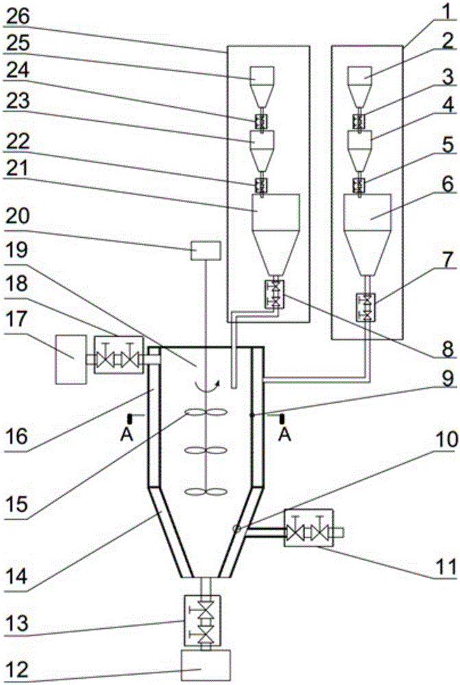
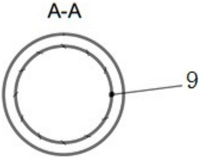
[0033] This embodiment provides a device for rapidly and continuously preparing droplet microspheres, such as figure 1 As shown, the equipment includes a dispersed phase feeding device 1, a continuous phase feeding device 26, a continuous phase pressure tank 19 and a rotary agitation device. The top of the continuous phase pressure tank 19 is in communication with the continuous phase feeding device 26, and the continuous phase pressure tank The bottom of 19 is provided with a discharge port, and the side wall of the continuous phase pressure tank 19 is provided with a discharge port, dispersed phase inlet hole 9 and air distribution hole 10 from top to bottom, the dispersed phase feeding device 1 and the dispersed phase The inlet hole 9 is connected, and the rotary stirring device is arranged in the continuous phase pressure tank 19.

[0034] Among them, the dispersed phase feeding device 1 includes a dispersed phase atmospheric storage tank 2, a dispersed phas...

Example Embodiment

[0043] Example 2:

[0044] This embodiment provides a device for rapidly and continuously preparing droplet microspheres. The structure is as described in Embodiment 1, and the difference is that the continuous phase pressure tank 19 includes an upper cylindrical tank body and a lower truncated cone-shaped tank. The dispersed phase inlet hole 9 is located on the side wall of the cylindrical tank, and the air distribution hole 10 is located on the side wall of the truncated cone-shaped tank.

Example Embodiment

[0045] Example 3:

[0046] A. The specific operation steps of disperse phase continuous feeding are as follows:

[0047] (1) Add the dispersed phase to the dispersed phase normal pressure storage tank 2, close the double valve 5 between the dispersed phase buffer storage tank 4 and the dispersed phase high pressure storage tank 6, and open the dispersed phase normal pressure storage tank 2 The double valve 3 between and the dispersed phase buffer storage tank 4, the dispersed phase flows from the dispersed phase atmospheric storage tank 2 into the dispersed phase buffer storage tank 4;

[0048] (2) When the dispersed phase in step (1) enters the 3 / 4 position in the dispersed phase buffer storage tank 4, close the double valve between the dispersed phase atmospheric storage tank 2 and the dispersed phase buffer storage tank 4 3. Press into the dispersed phase buffer storage tank 4;

[0049] (3) After the pressure in the dispersed phase buffer storage tank 4 is the same as the pressure...


PUM


Abstract

The invention relates to equipment for rapidly and continuously manufacturing droplet microspheres and application thereof. The equipment comprises a dispersed phase feeding device, a continuous phase feeding device, a continuous phase pressure tank and a rotating stirring device. The top of the continuous phase pressure tank is communicated with the continuous phase feeding device. The bottom of the continuous phase pressure tank is provided with an unloading opening. The side wall of the continuous phase pressure tank is provided with a discharging opening, a dispersed phase inlet hole and a ventilation hole from top to bottom. The dispersed phase feeding device is communicated with the dispersed phase inlet hole, and the rotating stirring device is arranged in the continuous phase pressure tank. According to the equipment for rapidly and continuously manufacturing droplet microspheres and the application, continuous phases and dispersed phases are conveyed into the continuous phase pressure tank continuously to achieve rapid and continuous material supply, and rotating blades play a role in assisting in material supply, so that working efficiency is improved; liquid drops are brought into a discharge device through inlet air in an air chamber, and the droplet microspheres are prepared efficiently, rapidly and continuously.

Description

Technical field [0001] The invention relates to a device for rapidly and continuously preparing droplet microspheres and its application, and belongs to the technical field of droplet microsphere preparation. Background technique [0002] Micro-droplets have many excellent properties such as small size, no diffusion between droplets, avoiding cross-contamination between droplets, stable reaction conditions, controllable mixing and many other excellent properties, and are more and more widely used. The droplet size uniformity (monodispersity) obtained by traditional mechanical stirring and colloid milling methods is poor; the microfluidic technology based on hydrodynamics is currently the main method for producing monodisperse microdroplets, but the rate is at ml / H level, although the micro-droplet growth rate can be improved by integrated micro-channels, it is still difficult to reach the order of l / h, and the mutual influence between multiple channels is large, which reduces th...

Claims


Application Information

Patent Timeline
IPC IPC(8): B01J13/04
Inventor 杨春振陈成敏刘光霞王立秋许敏
Owner ENERGY RES INST OF SHANDONG ACAD OF SCI
Why Eureka
Try Eureka